Configure the module – Rockwell Automation 1746-NR4 SLC RTD/Resistance Input Module User Manual User Manual
Page 29
Publication 1746-UM008B-EN-P - December 2006
Quick Start Guide 29
Configure the Module
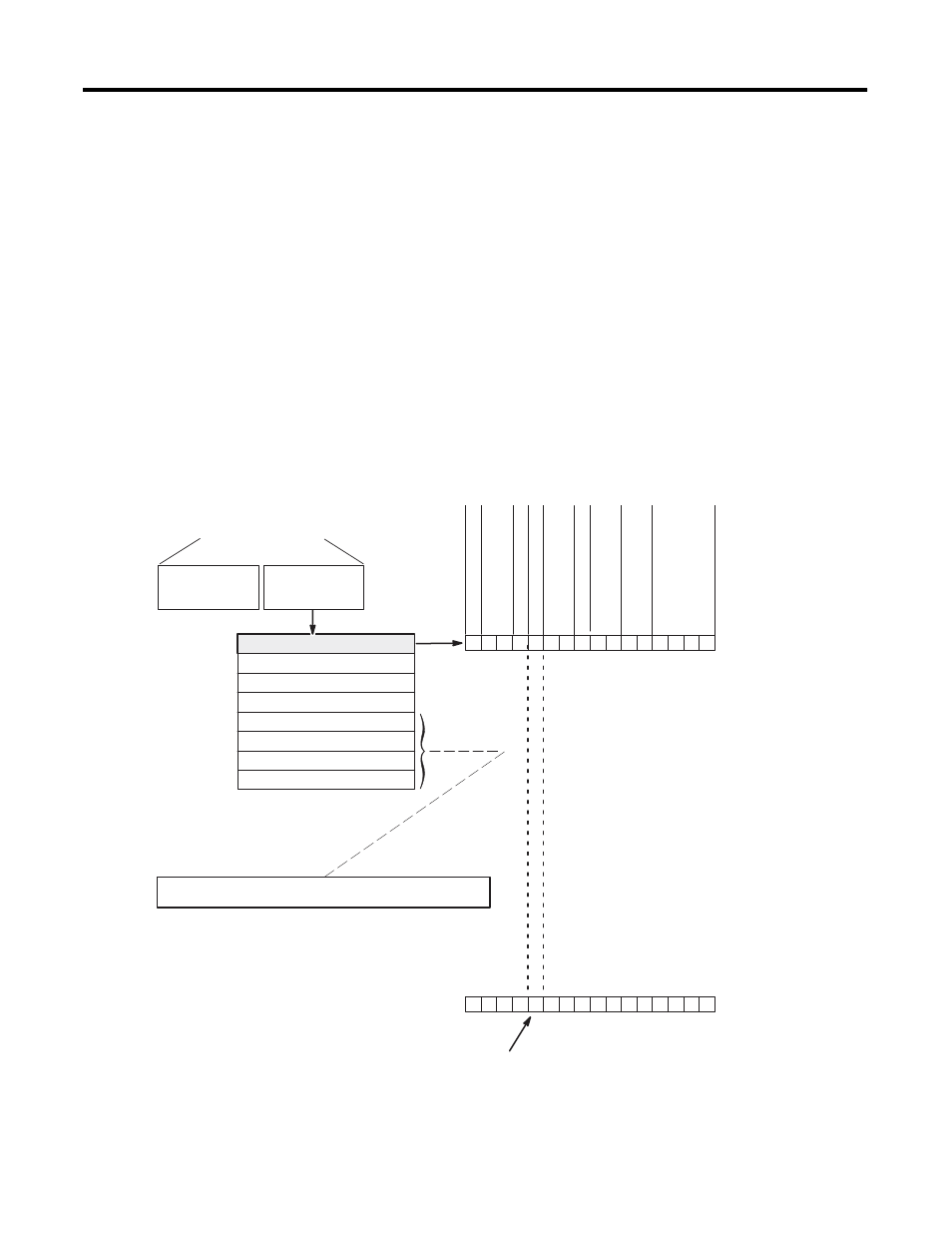
Determine the operating parameters for channel 0. In this example,
the figure shows the channel 0 configuration word defined with all
defaults (0) except for channel enable (bit 11). The addressing reflects
the location of the module as slot 1.
For details on how to configure the module for your application, refer
to chapter 4 and chapter 5.
A configuration worksheet is included on page 132 to assist you in
channel configuration.
For more information refer to chapter 5, Channel Configuration, Data,
and Status.
Output Image Detail
O:1.1
Channel 1 Configuration Word
Channel 2 Configuration Word
Channel 3 Configuration Word
Output Image
SLC 500 Controller
Data Files
Bit 15
Bit 0
Word 1
Word 2
Word 3
Address
O:1.0
Input Image
0 0 0 0 0 0 0 0 0 0 0 0 0 0 0 0
Channel 0 Configuration Word
Word 0
Input T
ype
Select
Data Format Select
Broken Input Select
Temperature Units Select
Filter Frequency Select
C
hannel Enable
(8 words)
0 0 0 0 1 0 0 0 0 0 0 0 0 0 0 0
Default Settings
New Setting
Set this bit (11) to enable channel. Address = O:1.0/11
• 100 Platinum R TD (385)
• Engineering Units x 1 (0.1 ˚/ step)
• Broken Input (set data word to zero)
• Degrees Celsius ( ˚C)
• 10 Hz Filter Frequency
• Channel Disabled
• 2.0 mA Excitation Current
• Module Defined Scaling
O:1.2
O:1.3
User-set Lower Scale Limit Range 0
Word 4
O:1.4
User-set Upper Scale Limit Range 0
Word 5
O:1.5
Word 6
O:1.6
Word 7
O:1.7
Bit 15
Bit 0
Excitation
C
urrent Select
Scaling Select *
Not Defined
If proportional counts data format is used, then output words 4…7
can be used to define a user-set scaling range for each channel.
* Scaling Select bits apply to proportional counts mode.
Limit Scale W ords are only used if scaling select = 01
or
10 and
data format = 11.
User-set Upper Scale Limit Range 1
User-set Lower Scale Limit Range 1