128 co, Channel configuration worksheet – Rockwell Automation 1746-NR4 SLC RTD/Resistance Input Module User Manual User Manual
Page 128
Publication 1746-UM008B-EN-P - December 2006
128 Configuration Worksheet for RTD/Resistance Module
11. Build the channel configuration word for every channel that is
being used on each RTD module repeating the procedures given
in steps 1…10.
12. Enter the completed configuration words for each module into
the summary worksheet on the following page.
13. Following the steps outlined in Chapter 6, Ladder Programming
Examples, enter this configuration data into your ladder program
and copy it to the RTD module.
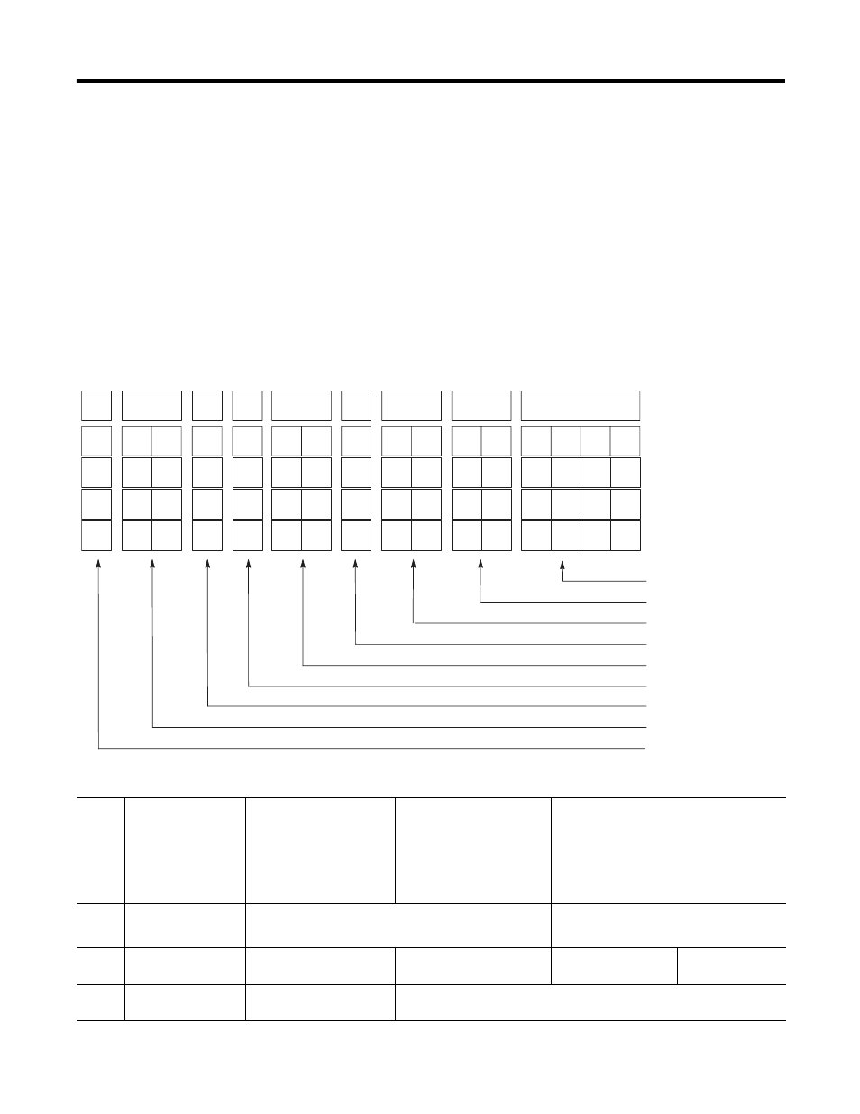
Channel Configuration Worksheet
Input Type Select
Data Format Select
Broken Input Select
Temperature Units Select
Filter Frequency Select
Channel Enable
Excitation Current Select
Scaling Select
Not Used
11
12
13
14
15
9
10
8
6
7
4
5
2
3
Bit Number
Channel 0
Channel 1
Channel 2
Channel 3
0
0
0
0
0
1
Bit Definitions
Bits
0…3
Input Type Select
0000 = 100
Ω Pt. (385)
0001 = 200
Ω Pt. (385)
0010 = 500
Ω Pt. (385)
0011 = 1000
Ω Pt. (385)
0100 = 100
Ω Pt. (3916)
0101 = 200
Ω Pt. (3916)
0110 = 500
Ω Pt. (3916)
0111 = 1000
Ω Pt. (3916)
1000 = 10
Ω Cu (427)
(1)
1001 = 120
Ω Ni (618)
(2)
1010 = 120
Ω Ni (672)
1011 = 604
Ω Ni-Fe (518)
1100 = 150
Ω
1101= 500
Ω
1110= 1000
Ω
1111= 3000
Ω
Bits 4
and 5
Data Format Select
00 = engineering units, x1
(3)
01 = engineering units, x10
(4)
10 = scaled-for-PID (0…16,383)
11 = proportional counts(-32,768…32,767)
Bits 6
and 7
Broken Input Select
00 = zero
01 = upscale
10 = downscale
11 = invalid
Bit 8
Temperature Units
Select
0 = degrees Celsius
1 = degrees Fahrenheit