Terminal wiring, Nr4 wiring considerations – Rockwell Automation 1746-NR4 SLC RTD/Resistance Input Module User Manual User Manual
Page 40
Publication 1746-UM008B-EN-P - December 2006
40 Install and Wire the Module
Terminal Wiring
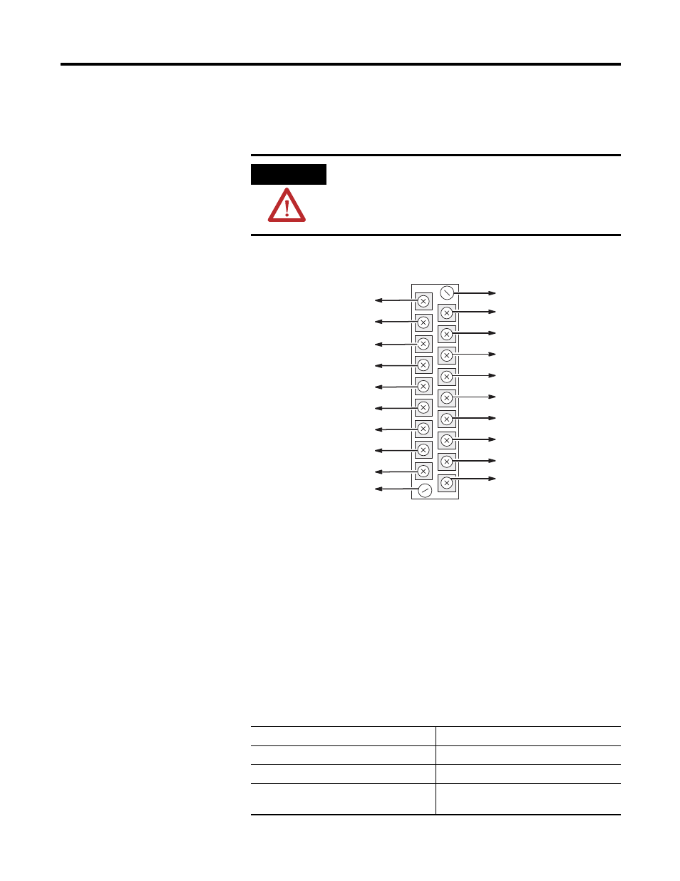
The RTD module contains an 18-position, removable terminal block.
The terminal pin-out is shown in RTD Connections to Terminal Block
on page 42.
Terminal Block
NR4 Wiring Considerations
Follow the guidelines below when planning your system wiring.
Since the operating principle of the RTD module is based on the
measurement of resistance, take special care in selecting your input
cable. For 2–wire or 3–wire configuration, select a cable that has a
consistent impedance throughout its entire length.
ATTENTION
Disconnect power to the SLC before attempting to install,
remove, or wire the removable terminal wiring block.
To avoid cracking the removable terminal block, alternate the
removal of the terminal block release screws.
Cable Selection
Configuration
Recommended Cable
Two-wire
Belden #9501 or equivalent
Three-wire less than 30.48 m (100 ft)
Belden #9533 or equivalent
Three-wire greater than 30.48 m (100 ft) or
high humidity conditions
Belden #83503 or equivalent
Shield
Channel 0 RTD
Channel 0 Sense
Channel 0 Return
Shield
Channel 2 RTD
Channel 2 Sense
Channel 2 Return
Shield
Release Screw
Max. Torque =
0.6 Nm (5.3 in-bs)
Release Screw
Max. Torque =
0.6 Nm (5.3 in-bs)
Shield
Channel 1 RTD
Channel 1 Sense
Channel 1 Return
Shield
Channel 3 RTD
Channel 3 Sense
Channel 3 Return
Shield