Module addressing, 1762-ir4 configuration file, Appendix b – Rockwell Automation 1762-IR4 RTD/Resistance Input Module User Manual
Page 83: Configuring the 1762-ir4 module using rslogix 500, I1:e.4/2, Appendix
1
Publication 1762-UM003A-EN-P - February 2003
Appendix
B
Configuring the 1762-IR4 Module Using
RSLogix 500
This appendix examines the 1762-IR4 module’s addressing scheme
and describes module configuration using RSLogix 500.
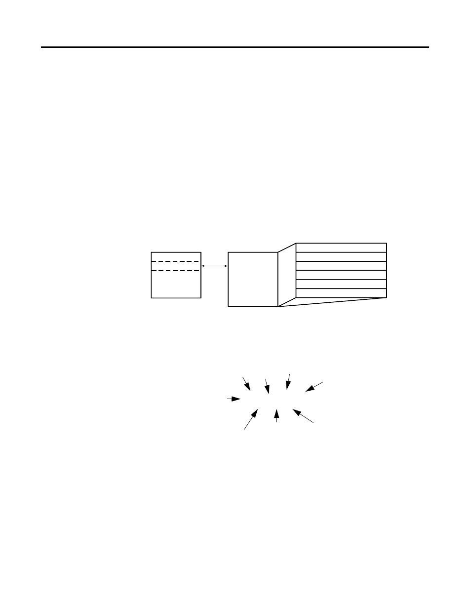
Module Addressing
The following memory map shows the input image table for the
module. Detailed information on the image table is located in
Chapter 3.
For example, to obtain the general status of Channel 2 of the module
located in slot e, use address I:e.4/2.
1762-IR4 Configuration File
The configuration file contains information you use to define the way
a specific channel functions. The configuration file is explained in
more detail in Configuring Channels on page 3-5.
The configuration file is modified using the programming software
configuration screen. For an example of module configuration using
RSLogix 500, see Configuration Using RSLogix 500 Version 5.50 or
Higher on page B-2.
Channel 3 Data Word
Channel 2 Data Word
Channel 0 Data Word
Word 0
Word 1
Word 2
Word 3
Word 4
Word 5
Channel 1 Data Word
Input Image
6 words
slot e
Input Image
File
General/Open-Circuit Status Bits
Over-/Under-range Bits
bit 15
bit 0
I1:e.4/2
File Type = Input
Slot
Element Delimiter
Word Delimiter
Word
Bit Delimiter
Bit
Data File Number