Rockwell Automation 1762-IR4 RTD/Resistance Input Module User Manual
Page 33
Publication 1762-UM003A-EN-P - February 2003
Installation and Wiring 2-15
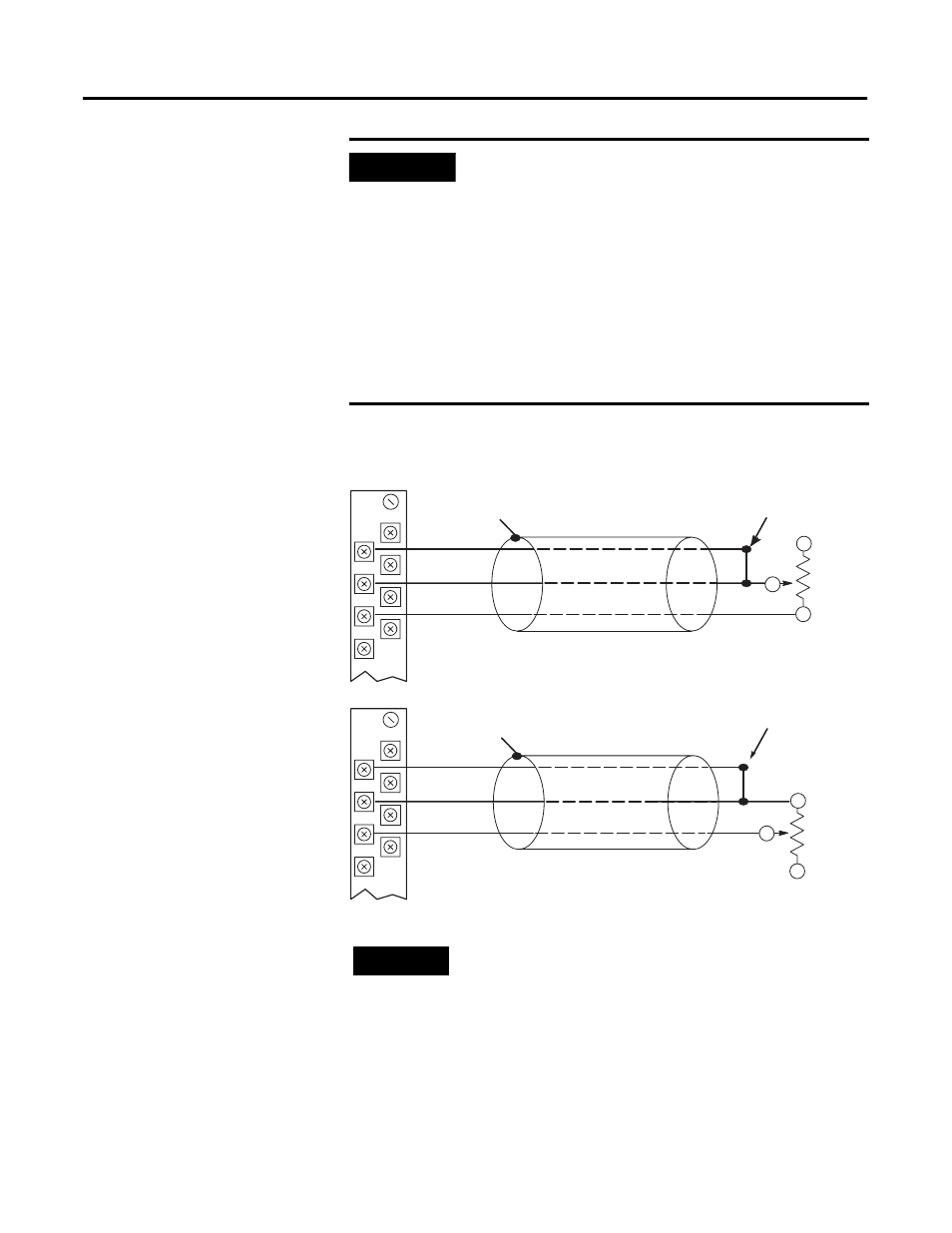
3-Wire Potentiometer Interconnection
IMPORTANT
Using 2-wire configurations does not permit the
module to compensate for resistance error due to
lead wire length. The resulting analog data includes
the effect of this uncompensated lead wire resistance.
The module continues to place the uncompensated
analog data in the input data file, but the open-circuit
status bit (OCx) is set in word 4 of the input data file
for any enabled channel using a 2-wire configuration.
These status bits may be used in the control program
to indicate that the analog data includes error due to
uncompensated lead wires. See page 3-4 for a
detailed discussion of the open-circuit status bits.
EXC 2
SENSE 2
RTN 2
NC
EXC 2
SENSE 2
RTN 2
NC
Cable Shield (to Ground)
Potentiometer
RTD EXC
Return
Sense
Run RTD and sense wires from the module to
potentiometer terminal and tie terminal to one point.
Cable Shield (to Ground)
Potentiometer
RTD EXC
Return
Sense
Run RTD and sense wires from the module to
potentiometer terminal and tie terminal to one point.
Belden 83503 or 9533 Shielded Cable
Belden 83503 or 9533 Shielded Cable
TIP
The potentiometer wiper arm can be connected to
either the EXC or return terminal depending on
whether you want increasing or decreasing
resistance.