Module operation -8 module field calibration -8, Module operation, Module field calibration – Rockwell Automation 1762-IR4 RTD/Resistance Input Module User Manual
Page 18
Publication 1762-UM003A-EN-P - February 2003
1-8 Overview
Module Operation
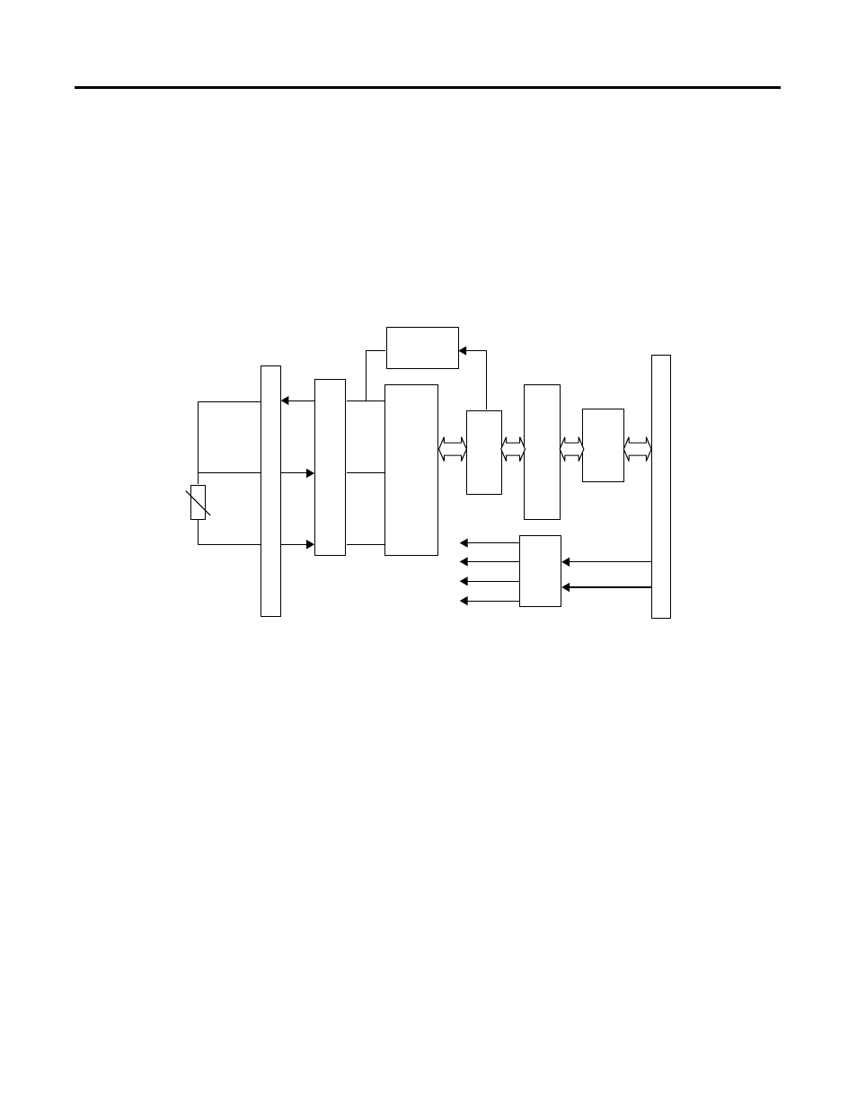
As shown in the block diagram below, each input channel of the
module consists of an RTD/resistance connection that accepts
excitation current; a sense connection that detects lead wire
resistance; and a return connection. The signals are multiplexed to an
A/D converter that reads the RTD or resistance value and the lead
wire resistance.
From the readings taken by the converter, the module returns an
accurate temperature or resistance to the controller user program
through the microprocessor. The module uses two bidirectional serial
ports for communication, each using an optocoupler for isolation. A
third optocoupler is used to reset the microprocessor if the module
detects a loss of communication.
Module Field Calibration
The input module performs autocalibration when a channel is initially
enabled. Autocalibration compensates for offset and gain drift of the
A/D converter caused by temperature change within the module. An
internal, high-precision, low drift voltage and system ground reference
is used for this purpose. In addition, you can program the module to
perform a calibration cycle once every 5 minutes. See Selecting
Enable/Disable Cyclic Autocalibration (Word 4, Bit 0) on page 3-20 for
information on configuring the module to perform periodic
calibration.
Input
EXC
SENSE
RTN
Multipl
exer
Current
Source
A/D
Converter
MCU
ASIC
BU
S
Isolat
io
n
Po
wer
Sup
pl
y
Te
rm
in
al
Op
to
-c
ou
pl
er
+24V dc
S-GND
+15V
+5V
A-GND
-15V