3 - module data, status, and channel configuration, Module memory map, Chapter 3 – Rockwell Automation 1762-IR4 RTD/Resistance Input Module User Manual
Page 35: Module data, status, and channel configuration, Module memory map -1, Chapter
1
Publication 1762-UM003A-EN-P - February 2003
Chapter
3
Module Data, Status, and Channel
Configuration
After installing the 1762-IR4 RTD/resistance input module, you must
configure it for operation, usually using the programming software
compatible with the controller (for example, RSLogix 500™). Once
configuration is complete and reflected in ladder logic, you will need
to get the module up and running and then verify its operation. This
chapter includes information on the following:
•
module memory map
•
accessing input image file data
•
configuring channels
•
configuring periodic calibration
•
preparing ladder logic to reflect the configuration
•
running the module
•
verifying the configuration
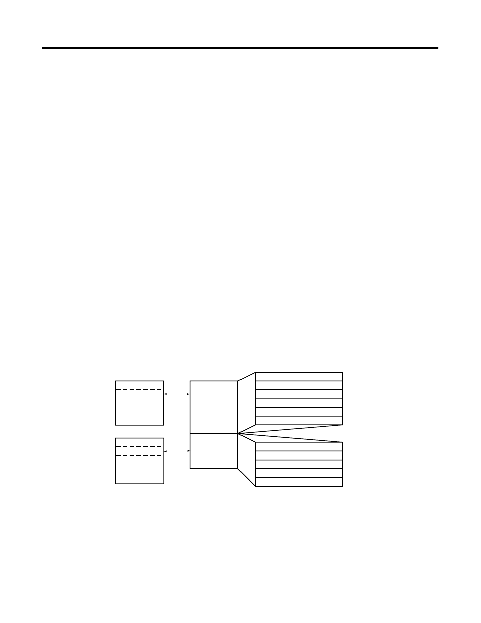
Module Memory Map
The module uses six input words for data and status bits (input
image), and five configuration words.
Channel 2 Data Word
Channel 0 Data Word
Word 0
Word 1
Word 2
Word 3
Word 4
Word 5
Channel 1 Data Word
Channel 3 Data Word
Channel 0 Configuration Word
Channel 1 Configuration Word
Channel 2 Configuration Word
Channel 3 Configuration Word
Word 0
Word 1
Word 2
Word 3
Input Image
6 words
Configuration
File
5 words
slot e
slot e
Input Image
File
Configuration
File
Bit 15
Bit 0
General/Open-Circuit Status Bits
Over-/Under-range Bits
Enable Calibration Word
Word 4