Rockwell Automation 1420 PowerMonitor 500 User Manual
Page 28
28
Rockwell Automation Publication 1420-UM001D-EN-P - September 2013
Chapter 3
Unit Configuration
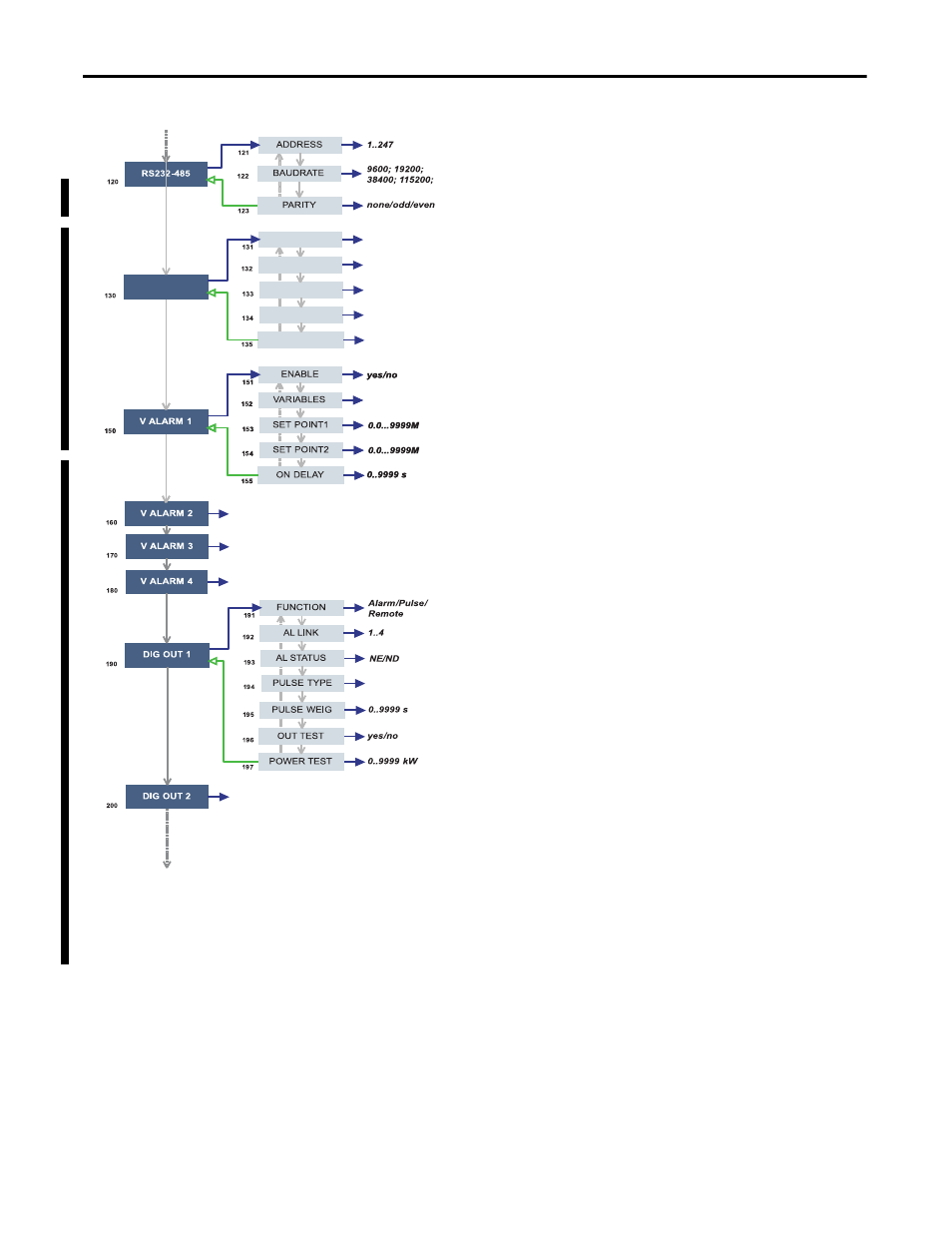
• 120 RS232-485: User settings for the RS-232 and
RS-485 serial communication ports.
• 130 ETHERNET: User settings for the Ethernet
communication port.
• 150 VIRT AL 1: This function lets you set the alarm
parameters.
– 151 ENABLE: enable (YES) or disable (NO) the
alarm.
– 152 VARIABLES: set the variable to be linked to
the alarm.
– 153 SET 1:set the on alarm set point of the variable.
– 154 SET 2: set the off alarm set point of the variable.
– 155 ON DELAY: set a delay on activation of the
alarm.
• 190 DIG OUT 1: This function lets you link a virtual
alarm to the digital output and to its working
parameters.
– 191 FUNCTION:
Alarm - the digital output is enabled when the
associated alarm status occurs.
Pulse - the measured energy is retransmitted by the
digital output by means of pulses.
Remote - the digital output can be controlled
through a command sent through the serial
communication port.
– 192 AL LINK: select the virtual alarm that it has to
be associated.
– 193 AL STATUS: ‘ND’ (normally de-energized
relay) or ‘NE’ (normally energized relay).
– 195 PULSE WEIG: selects the pulse weight (kWh
per pulse).
– 196 OUT TEST: Tests the digital output. YES
enables the test, No disables the test.
– 197 POWER TEST: sets a simulated power value
(kW) to test the energy pulse output. The function
remains active until you exit the programming
menu.
list of available
variables
list of available
variables
As DIG OUT 1
As VIRT ALARM 1
As VIRT ALARM 1
As VIRT ALARM 1
list of available
variables
-IP ADDRESS
-SUBNET
-GATEWAY
-TCP IP PRT
-ACD
ETHERNET
www.xxx.yyy.zzz
www.xxx.yyy.zzz
www.xxx.yyy.zzz
1…9999 (default = 502)
yes/no (default = no)