Additional button functions, Display features, Display indications – Rockwell Automation 1420 PowerMonitor 500 User Manual
Page 12
12
Rockwell Automation Publication 1420-UM001D-EN-P - September 2013
Chapter 1
PowerMonitor 500 Overview
Additional Button Functions
Certain buttons have two functions. To access the second function, press and
hold the button for more than 2 seconds.
Displays PowerMonitor 500 information screens, which provide reference
standards, firmware revision, and year of manufacture.
Resets the MAX (maximum) of the displayed variables.
Resets the dmd (demand) of the displayed variables.
To perform a reset, press this button to confirm.
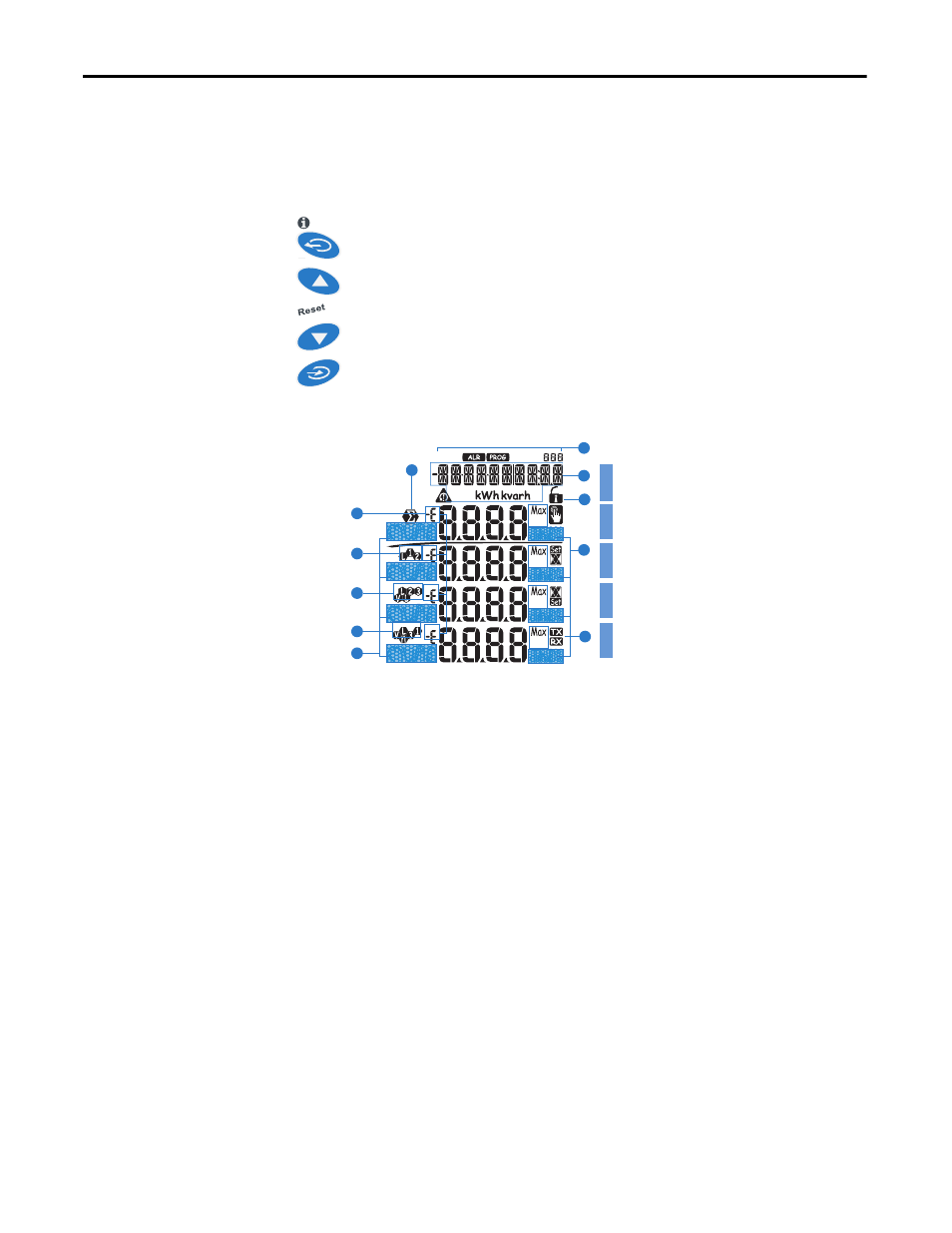
Display Features
Display Indications
1. Phase displacement indicator: inductive L, -L, or capacitive C, -C.
The sign is based on the direction of real power flow. Positive = consuming
power, negative = generating power.
2. Indicates the measured value phase (phase-neutral L1 or phase-phase L12).
3. Indicates the measured value phase (phase-neutral L2, phase-phase L23, or
unbalance phase-phase VLL).
4. Indicates the measured value phase (phase-neutral L3, phase-phase L31, or
unbalance phase-neutral VLn).
5. Engineering unit and multiplier indicator (k, M, V, W, A, var, PF, Hz, An).
6. ALR: the alarm display function is active. PROG: the programming
function is active.
7. Area set aside for energy counters (see table on the following screen), text
messages, date and time (format: dd.mm.yy/hh:mm).
8. Indicates metering values are dmd (demand) or MAX (maximum) values.
2
3
4
5
6
7
11
8
1
9
LI
N
E
1
LI
N
E
2
LI
N
E
3
LI
N
E
4
L
IN
E
5
12