Before mounting your drive, Interconnect, Cable – Rockwell Automation 1336T Master/Slave Parallel AC Drv User Manual
Page 14: Encoder cable
1336 FORCE-5.19 – August, 2000
2-2
Mounting and Wiring Your 1336 FORCE Master/Slave Drive
Before Mounting Your Drive
Before mounting your drive, consider the following:
•
what tools and equipment you need to mount your drive
•
the distance between the motor and the drive
•
the distance between the drive and other surfaces
Mounting
The Slave drive is intended to be mounted adjacent to the Master
drive. Both the Master and the Slave drive should be located near the
converter (common bus supply).
Mounting clearances for 1336 FORCE Master/Slave Drives are the
same as the requirements for standard G and H frame drives. Refer to
Chapter 2 of the 1336T User Manual (1336 FORCE 5.12) for
guidelines on mounting and heat dissipation requirements.
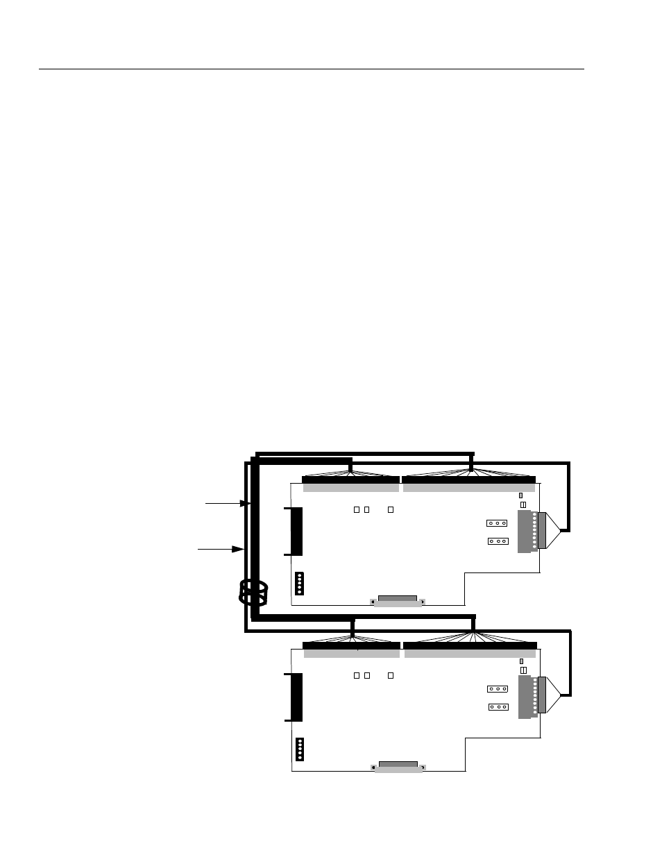
Interconnect Cable Connection
The interconnect cable which runs from the TB12 and TB13
connectors on the Master Main Control Board to the TB12 and TB13
connectors on the Slave Main Control board should be pre-installed
and routed thru a ferrite core on the top of each cabinet. Check that
this cable is connected at both ends and routed correctly thru the
ferrite cores before starting the drive. A disconnected cable will cause
a drive fault at power-up.
If a new interconnect cable is either installed or replaced on-site, the
length of the new or replacement cable must Not exceed 10 ft.
TB12
TB10
J5
J7
TB11
5V
12V
5V
12V
1 2 3
1
2 3
J3
J4
Master
EN VP
CP
TB13
J1
Main Control Board (Master Drive)
TB12
TB10
J5
J7
TB11
5V
12V
5V
12V
1 2 3
1
2 3
J3
J4
Slave
EN VP
CP
TB13
J1
Main Control Board (Slave Drive)
Interconnect
Cable
Ferrite
Core
Encoder
Cable