Rockwell Automation 1502 Medium Voltage Contactor, 800A (Series D and E) User Manual
Page 46
Maintenance
4-17
1502-UM051E-EN-P – June 2013
1. Make sure the contactor is in the open (or tripped) state.
2. Remove latch pivot bolt with a 3/16" Allen key as shown in Figure 4.21, and
remove the lever assembly. The latch spring is no longer retained at this
point and may fall out of the core – do not misplace this spring.
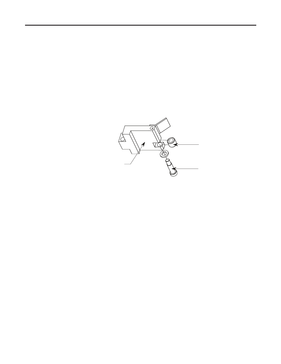
3. Remove the roller mounting bolt as shown in Figure 4.23 allowing the roller
to be removed.
4. Insert the new roller and install the roller mounting bolt.
5. Make sure that the latch spring is seated properly in the core, position the
lever assembly and install the latch pivot bolt. The spring must be seated
properly in the retaining holes in both the core and the lever.
Trip Coil Lever
Roller mounting bolt
Latch roller
Figure 4.23 – Mechanical Latch Assembly
With the exception of the roller, the latch mechanism will last the rated life of
the contactor. If the contactor is used beyond the rated life, the latch mecha-
nism should be refurbished by replacing the lever assembly, latch spring and the
armature plate. These parts can be ordered pre-assembled as Refurbishing Kit
#80158-058-51.
1. Remove latch pivot bolt with a 3/16" Allen key as shown in Figure 4.21, and
remove the lever assembly. The latch spring is no longer retained at this
point and can be removed and discarded.
2. Make sure that the new latch spring is seated properly in the core; position
the new lever assembly and install the latch pivot bolt. The spring must be
seated properly in the retaining holes in both the core and the lever.
3. Loosen the locking nut on the return spring compression bolt and withdraw
the compression bolt until the return spring is relaxed. Remove the return
spring as shown in Figure 4.2.
4. Remove the armature plate mounting bolts. Discard the armature plate and
install the new armature plate. Reinstall the return spring and advance the
compression bolt until the armature plate makes contact with the stop as
shown in Figure 4.10. Advance the bolt one additional full turn to ensure
that the contactor opens fully. Holding the compression bolt in position with a
wrench, tighten the compression bolt locking nut.
Mechanical Latch Roller
Replacement Procedure
Mechanical Latch Mechanism
Refurbishing Procedure