Mechanical latch trip coil replacement procedure – Rockwell Automation 1502 Medium Voltage Contactor, 800A (Series D and E) User Manual
Page 44
Maintenance
4-15
1502-UM051E-EN-P – June 2013
8. The closing coil is the larger of the two (Series D only) and is located toward
the front of the contactor. Refer to the appropriate wiring diagram (Chapter
3 – Installation) to ensure that the bridge diode and/or MOV leads are
properly connected and for complete control wiring details.
9. Ensure that all leads, diodes and MOVs are secured tightly. Operate the
contactor several times to ensure that the core is located properly.
Before beginning work on the contactor, ensure that it is
isolated from all power sources and locked out, and that
the contactor is in the open (or tripped) state.
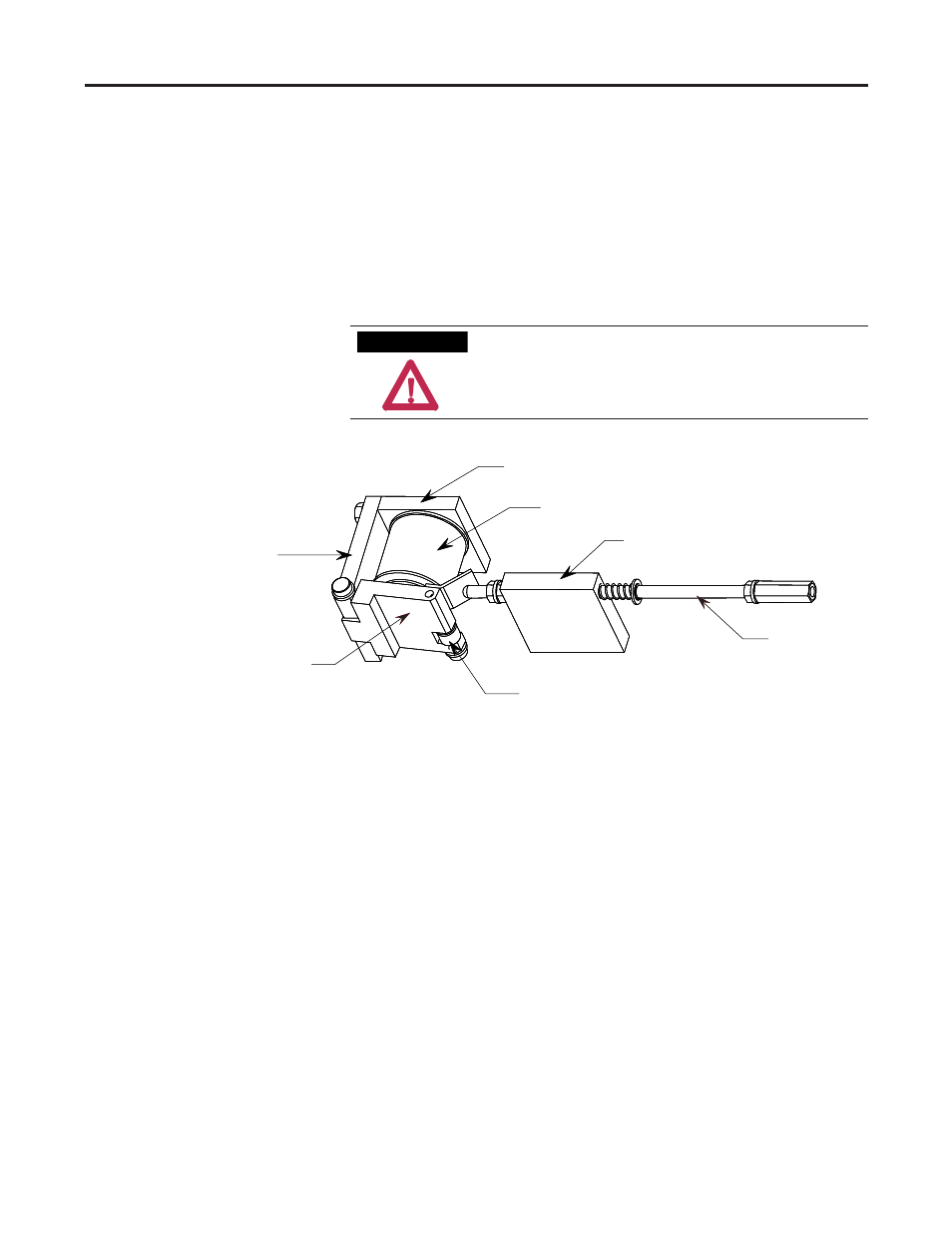
Figure 4.20 – Mechanical Latch Assembly
1. Disconnect the trip coil leads from the terminal block assembly. The trip
coil leads are the blue and white wires connected to terminals "B" and "D"
respectively (see Figure 4.18 or 4.19). Cut any wire ties fastening the leads to
the contactor base.
2. Remove latch pivot bolt with a 3/16" Allen key as shown in Figure 4.21, and
remove the lever assembly. The latch spring is no longer retained at this
point and may fall out of the core – do not misplace this spring.
3. Remove the trip core mounting bolt as shown in Figure 4.22 and slide the
core out of the coil allowing the coil to be removed.
4. Slide the core into the new coil and install the core mounting bolt.
Mechanical Latch Trip Coil
Replacement Procedure
A T T E N T I O N
Latch Lever Assembly
Yoke Plate
Latch Roller
Manual Trip Actuator
Manual Trip Guide Block
Trip Coil (core hidden)
Core Mounting Plate