Main coil replacement procedure – Rockwell Automation 1502 Medium Voltage Contactor, 800A (Series D and E) User Manual
Page 40
Maintenance
4-11
1502-UM051E-EN-P – June 2013
18. Operate the contactor several times to ensure proper function.
19. Wipe down the exterior surface of each vacuum bottle with a clean lint-free
cloth.
20. Replace the interphase barriers and retaining brace.
21. Again, account for all tools used during the above procedure. If any tools are
unaccounted for, do not energize the equipment.
Before beginning work on the contactor, ensure that it is
isolated from all power sources and locked out.
For the safety of maintenance personnel, remove the control wiring from the
contactor by disconnecting the control wire plug before starting any disassembly
of the contactor.
1. Disconnect the coil leads from the terminal block assembly. The closing and
hold-in coils are both wound on one bobbin, therefore, all four coil leads must
be removed (the MOVs and/or bridge diode leads may come loose as well).
See Figures 4.15 to 4.19 for the appropriate connections.
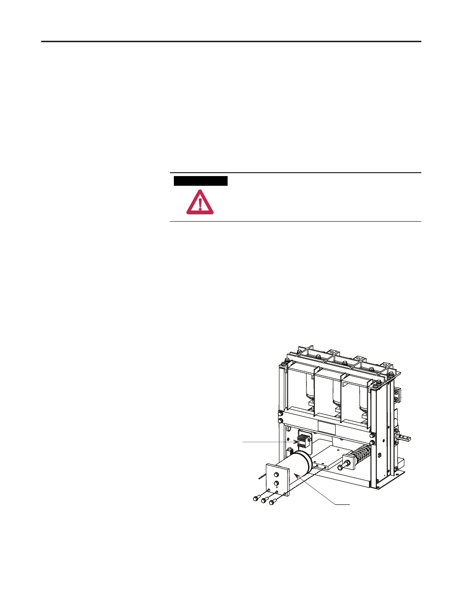
2. Remove the three bolts from the bottom of the magnet assembly and with-
draw the assembly from the contactor as shown in Figure 4.13.
Terminal block assembly
Magnet assembly
Figure 4.13 – Magnet Assembly Removed
Main Coil Replacement
Procedure
A T T E N T I O N