Main coil replacement procedure (cont.) – Rockwell Automation 1502 Medium Voltage Contactor, 800A (Series D and E) User Manual
Page 41
4-12
Maintenance
1502-UM051E-EN-P – June 2013
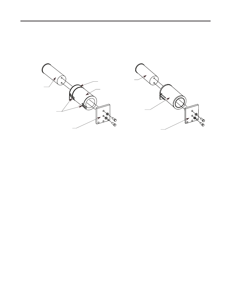
3. Remove the two bolts which connect the magnet core to the core mounting
plate as shown in Figure 4.14.
4. Slide the core out of the coil as shown in Figure 4.14. If there is a tight fit,
tap the core out with a hammer.
Core
Mounting Plate
Coil Leads
Series D
Hold-in Coil
Closing Coil
Core
Mounting Plate
Coil Lead
Series E
Figure 4.14 – Magnet Assembly
5. Slide the core into the new coil with the mounting hole end located towards
the closing coil. Ensure that the coil leads are oriented properly with respect
to the core mounting holes.
6. Bolt the core to the mounting plate and position the magnet assembly in the
contactor. Install the three (3) bolts which retain the assembly and torque
all bolts to 20 ft-lb.
7. Referring to Figures 4.15 and 4.16 for Series D or Figure 4.17 for Series E
electrically held contactors, connect the leads from the coil to the terminal
block assembly as follows:
Series D:
• Closing coil (yellow lead) to “C”
• Closing coil (black lead) to “D”
• Hold-in coil (yellow lead) to “P”
• Hold-in coil (blue lead) to “N”
Series E:
• Closing coil (yellow lead) to “C”
• Closing coil (black lead) to “N”
Main Coil Replacement
Procedure (cont.)