Rockwell Automation 1502 Medium Voltage Contactor, 800A (Series D and E) User Manual
Page 42
Maintenance
4-13
1502-UM051E-EN-P – June 2013
Referring to Figure 4.18 for Series D or Figure 4.19 for Series E mechanical-
ly latched contactors, connect the leads from the coil to the terminal block
assembly as follows:
Series D:
• Closing coil (yellow lead) to "H1"
• Closing coil (black lead) to "H2"
• Hold-in coil (yellow lead) to "C1"
• Hold-in coil (blue lead) to "C2"
• Trip Coil (white lead) to "D"
• Trip Coil (blue lead) to "B"
Series E:
• Closing coil (yellow lead) to "C"
• Closing coil (black lead) to "A"
• Trip Coil (white lead) to "D"
• Trip Coil (blue lead) to "B"
Note: The contactor will have either a high density (1492-HC6) or a regular
(1492-HJ86) terminal block. The wiring convention is the same for both types.
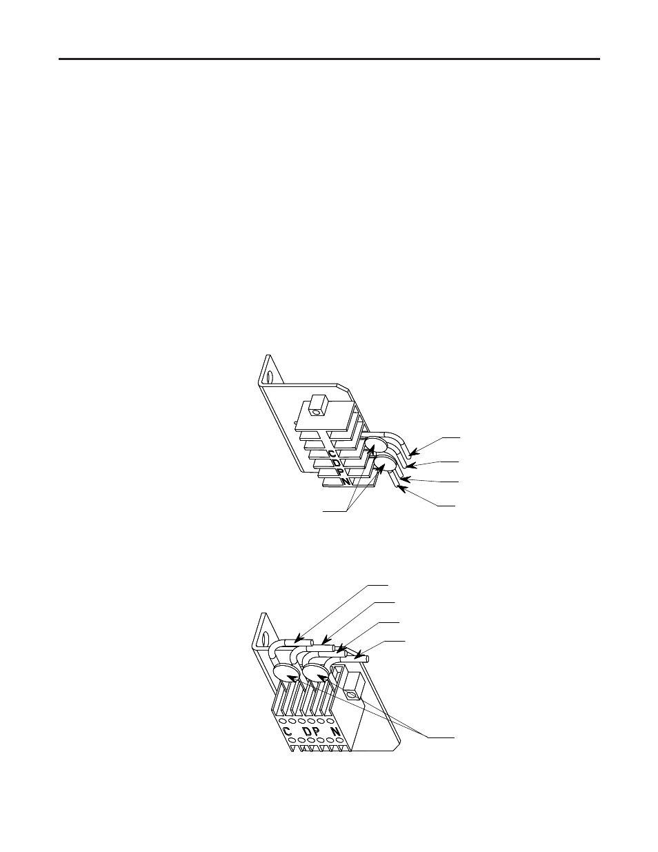
Hold -in coil (blue lead)
MOVs
Hold -in coil (yellow lead)
Closing coil (black lead)
Closing coil (yellow lead)
Figure 4.15 – Terminal Block Assembly (Electrically held Series D Contactor,
regular terminal block)
Hold -in coil (blue lead)
MOVs
Hold -in coil (yellow lead)
Closing coil (black lead)
Closing coil (yellow lead)
Figure 4.16 – Terminal Block Assembly (Electrically Held Series D Contactor,
high density terminal block)
Note: Figures 4.15 and 4.16 show the fast drop-out
configuration. The normal drop-out contactor has only
one (1) MOV.