Adjusting the normally open (isa) contacts – Rockwell Automation 1503 OEM Starter Frame Components Installation Manual User Manual
Page 43
1503-IN050D-EN-P – June 2012
Adjustments
3-9
ISa and ISb contacts are exactly the same (700 CPM). The cam controls the
normally open or normally closed status of the contacts.
Refer to Figures 2.10 to 2.13 for wiring diagrams.
Important: The Isolation Switch Ground Adjustment procedure (page 3-7)
must be completed before adjusting the auxiliary contacts to ensure proper
synchronization of the assembly.
Adjusting the Normally Open (ISa) Contacts
To avoid shock hazards, lock out incoming power
before working on the equipment. Verify with a hot stick
appropriate voltage measuring device that all circuits are
voltage free. Failure to do so may result in severe burns,
injury or death.
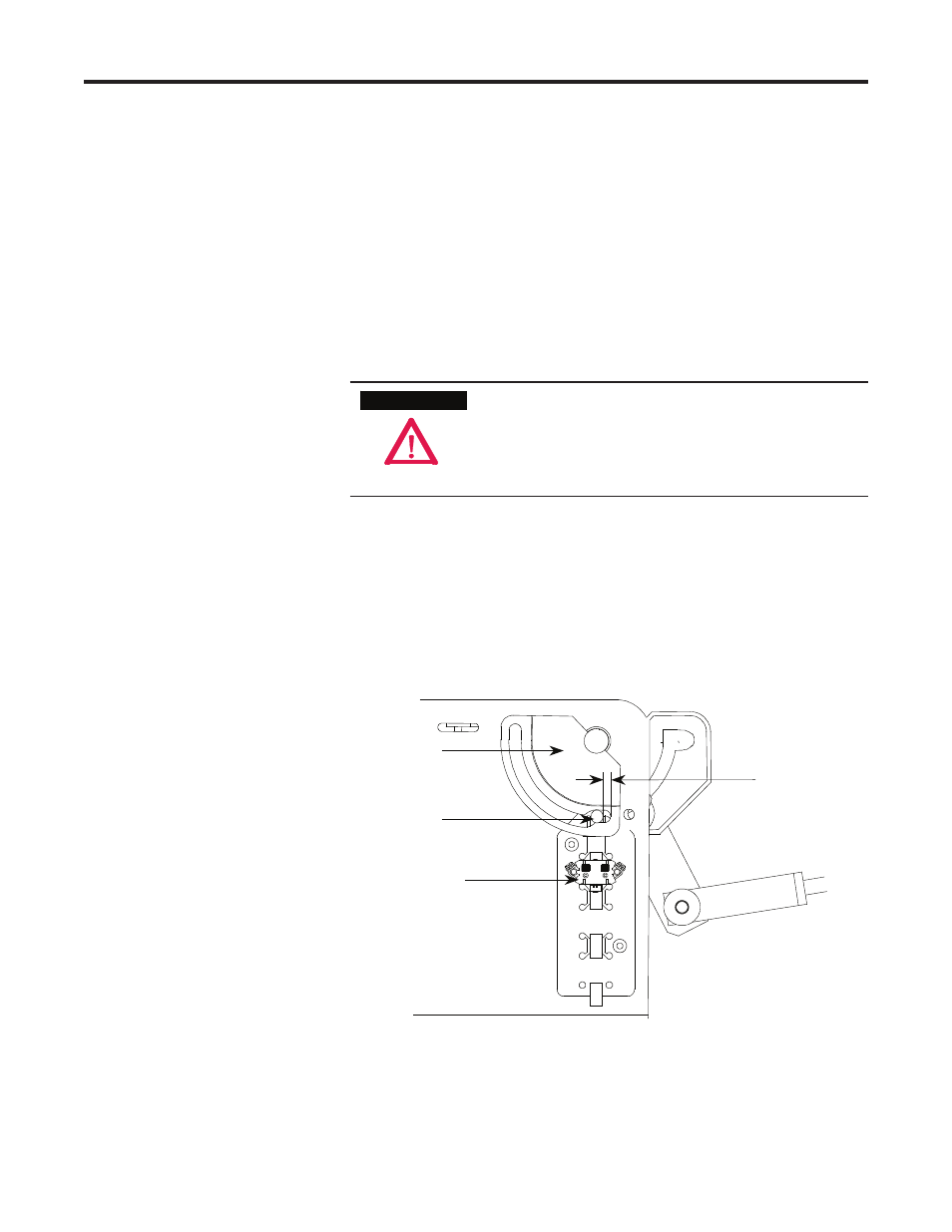
1) Move the isolation switch handle to the ON (closed) position.
2) Loosen the bolt holding the outside cam to the shaft. Do not loosen the
bolt entirely. The cam should not be able to rotate freely on the shaft.
3) Insert a 0.25 in. (6.35 mm) diameter pin into the cam groove between
the cam follower and the end of the cam groove.
CATA
LO
G NO
.
700-CPM
SER. A
20
AMP
Cam
Cam Follower
Auxiliary Contact
Gap
0.25 in.
(6.35 mm)
Left Side View
Figure 3.11 – Adjusting Auxiliary Contacts (Isa Auxiliary Contact Shown)
A T T E N T I O N
A T T E N T I O N