Mounting isolation switch handle module – Rockwell Automation 1503 OEM Starter Frame Components Installation Manual User Manual
Page 11
Component Installation 2-3
1503-IN050E-EN-P – June 2013
The handle is shipped in the OFF, or open, position. All
instructions assume the handle remains in the OFF
position during installation and adjustment procedures
unless otherwise stated.
Required Hardware:
• Six (6) ¼-20 x 0.5 in. (6.3 x 1.8 x 13mm Type B) self-tapping screws
• One (1) 5/16 in. (M8 x 1.25) grounding wire screw
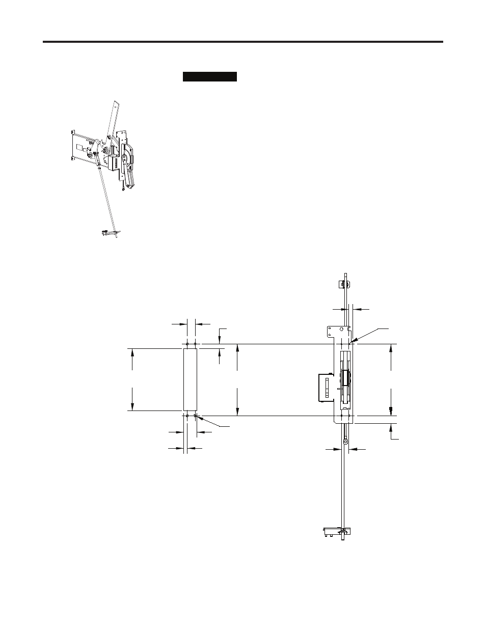
Refer to the component layout shown in Figure 2.1 or 2.2 to determine the
mounting location and the location of the mounting holes for the isola-
tion switch handle module. Refer to Figure 2.3 for a detailed view of the
mounting holes.
1) Prepare a cut-out in the cabinet for the handle using the dimensions
shown in Figure 2.3.
2) Drill four (4) 0.281-in. (6.8 mm) clearance holes in the locations indi-
cated for the retaining screws.
9.53
[242]
1.00
[25]
1.06
[27]
0.53
[14]
4 X 0.219 (5.31)
Ø
MOUNTING HOLES
1.74
[44]
1.00
[25]
8.26
[210]
9.53
[242]
0.48
[12]
0.65
[17]
4 X Ø 0.281 [6.8]
CLEARANCE HOLES
Front Mounting Surface
Cutout Dimensions
Figure 2.3 – Handle Cut-out Dimensions
Front View
(Handle cut away
to show lower
mounting holes)
Front Mounting Surface
Cutout Dimensions
Mounting Isolation Switch
Handle Module
I M P O R T A N T
I M P O R T A N T
Isolation Switch Handle
(OFF Position)