Rockwell Automation 1503 OEM Starter Frame Components Installation Manual User Manual
Page 25
Component Installation 2-17
1503-IN050E-EN-P – June 2013
7) Move the handle to the OFF position. Swing the door closed and
inspect the position of the Z-clip with respect to the handle pin.
8) Set the Z-clip so that it is just above the handle pin. Do not set the Z-clip
more than 0.125 in. (3 mm) above the pin. Tighten the screws.
9) Close the door and move the isolation switch handle to the ON posi-
tion. If the handle will not move to the ON position, the cover catch is
set too high and is not contacting the defeater lever. Open the door and
set the cover catch lower. Verify correct functioning.
10) Swing the door shut and move the isolation switch handle to the ON
position. Verify that the door interlock assembly is functioning properly.
The mechanical interlock is the primary safety mecha-
nism preventing access to the medium voltage power
cell. The mechanism also prevents opening or closing
the isolation switch under load (ie. it is a non-load-break
switch). A secondary electrical interlock is intended to
disengage the contactor in the event of a mechanical in-
terlock failure. See page 3-8 for additional information.
When properly connected, the isolation switch operating mechanism is
designed to provide the following safety features:
• Prevent the opening of any medium voltage door interlocked with the
mechanism while the handle is in the ON position and the unit is energized.
•
Prevent moving the handle to the ON position and energize the unit
while the medium voltage door is open.
•
Disengage the contactor from the RUN mode when the handle is
moved from the ON to OFF position.
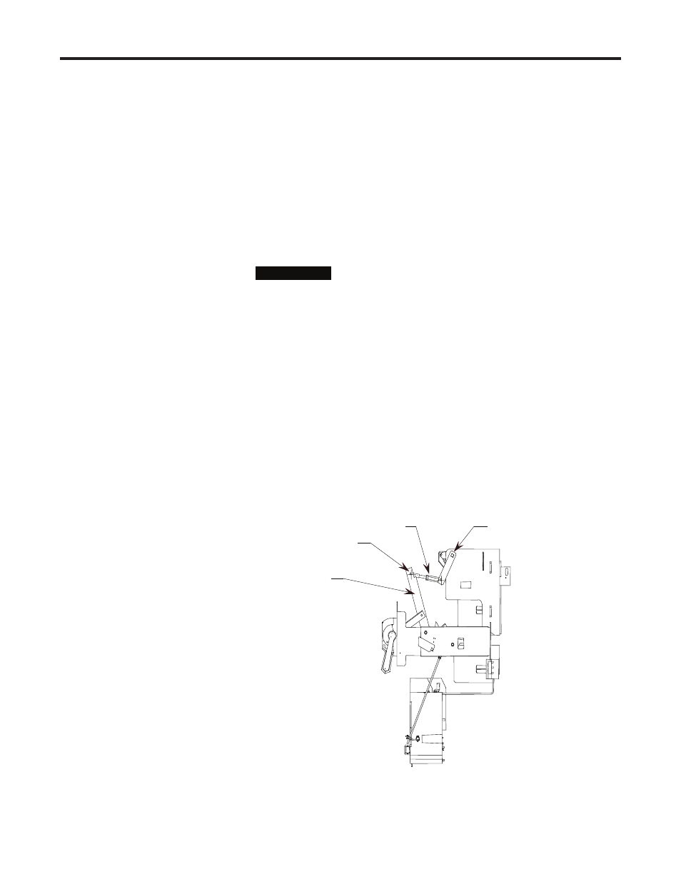
Right Side View
Connection Point
(Clevis and Cotter Pin)
Isolation Switch
Operating Lever
Connecting Rod
Disconnect Lever
Figure 2.16 – Handle Mechanism Connection
I M P O R T A N T
I M P O R T A N T
Connecting Isolation Switch
to Isolation Switch Handle