Door interlock assembly (cont.) – Rockwell Automation 1503 OEM Starter Frame Components Installation Manual User Manual
Page 24
2-16
Component Installation
1503-IN050E-EN-P – June 2013
All mounting hardware for the Door Interlock Assembly
is supplied. Metric equivalents are provided should the
user wish to substitute metric hardware.
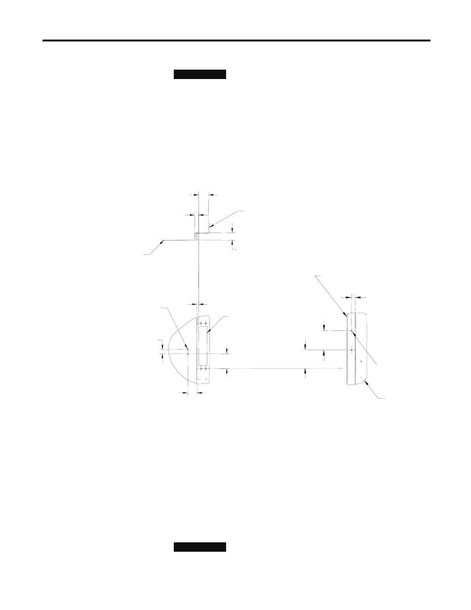
1) See Figure 2.15 for the mounting dimensions for the door interlock
assembly.
2) Drill two (2) 0.172 in. (4.6 mm) pilot holes on the right side of the door
for the Z-clip.
3) Drill two (2) 0.219 in. (5.5 mm) pilot holes on the front of the door for
the cover catch mounting bracket.
1.95
[49]
1.55
[39]
3.13
[80]
0.35
[9]
0.88
[22]
TOP VIEW
FRONT VIEW
See Fig. 2.3
Customer
supplied door
Customer supplied
structure
0.84
[21]
MAX.
2.11
[54]
MIN.
2 X Ø 0.219 [5.31]
Pilot Holes
(For rib-necked
carriage bolts)
3.38
[86]
3.50
[89]
0.65
[17]
RIGHT SIDE VIEW
2 X Ø 0.172 [4.09]
Pilot holes
Customer
supplied door
Customer supplied
structure
Figure 2.15 – Mounting Locations for Door Interlock Assembly
4) Attach the Z-clip using #10 (4.8 x 1.6 Type B) self-tapping screws, but
do not completely tighten them.
5) Attach the cover catch mounting bracket using #10-32 x 0.500
(M5 x 0.8) rib-necked carriage screws, lockwashers and hex nuts.
6) Attach the cover catch to the cover catch mounting bracket using the
supplied #10-32 x 0.219 pan-head machine screw.
The pilot holes in the cover catch are threaded. To avoid
damaging the thread, use the hardware provided to attach
the cover catch to the mounting bracket.
I M P O R T A N T
I M P O R T A N T
(All dimensions in inches [millimeters])
I M P O R T A N T
I M P O R T A N T
Door Interlock Assembly
(cont.)