Contactor, Control panel, Intellivac – Rockwell Automation 1503 OEM Starter Frame Components Installation Manual User Manual
Page 18
2-10
Component Installation
1503-IN050E-EN-P – June 2013
Contactor
Refer to the following publications for the Bulletin 1502 Medium Voltage
Contactor:
• 400A – Publication 1502-UM050_EN-P ( Series D)
• 400A – Publication 1502-UM052_EN-P (Series E)
• 800A – Publication 1502-UM051_EN-P (Series E)
These user manuals contain detailed information on installation, adjustment
and maintenance for this product.
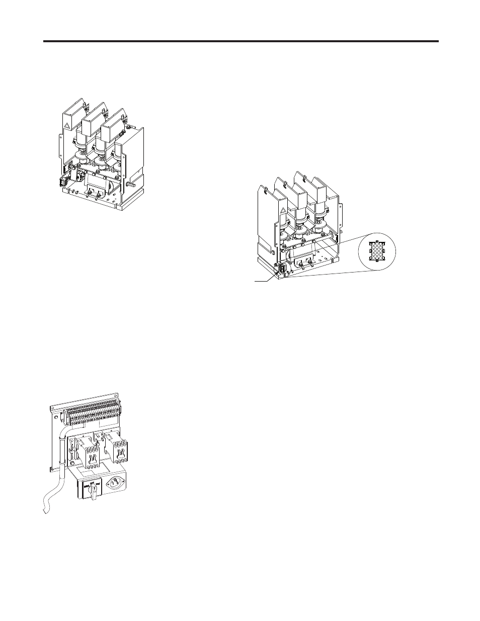
Figure 2.9 – 120V and 230V Control Wire Plug Location and Confi gurations
Note: Refer to the appropriate vacuum contactor User Manual for detailed
wire plug pin confi gurations.
Control Panel
Required Hardware:
– Four (4) 1/4-20 x 0.5 in. (6.3 x 1.8 x 13mm Type B) self-tapping screws
Mount the control panel in a suitable location. Be aware that the control plug
wiring harness is 10 ft. (3 meters) in length. Ensure that the wiring harness
route still allows for a proper connection to the contactor control plug.
Connect the control panel harness to the contactor control wire plug on the
lower left side of the contactor. The number codes on the plug must line up
with those on the contactor to ensure a proper connection. See Figure 2.9.
Use the terminal blocks on the control panel to connect the unit to a 120- or
230-volt grounded power source (whichever is applicable to the control panel)
and to other remote devices - see Figure 2.10 or 2.12 for electrical drawings.
IntelliVAC
Refer to Publication 1503-UM051_EN-P or 1503-UM052_-EN-P for
information regarding the IntelliVAC control module. Refer to Figure 2.12
or 2.13 for typical electrical drawings.
Contactor
Control Wire
Plug