Mounting isolation switch, And trailer fuse block (cont.) – Rockwell Automation 1503 OEM Starter Frame Components Installation Manual User Manual
Page 14
2-6
Component Installation
1503-IN050E-EN-P – June 2013
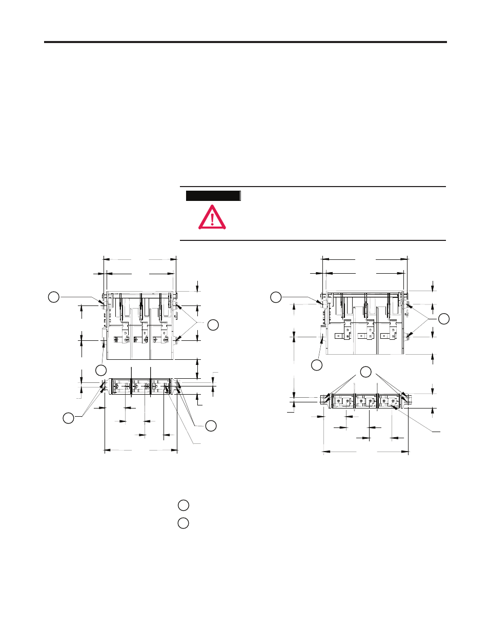
Mounting Isolation Switch
Refer to the component layout shown in Figure 2.1 or 2.2 to determine the
and Trailer Fuse Block (cont.)
location of the trailer fuse block. Refer to Figure 2.6 to determine the
location of the mounting holes for the trailer fuse block.
1) Drill four (4) 0.219 in. (5.5 mm) pilot holes at Location B as shown in
Figure 2.6 for the trailer fuse block.
2) Attach the trailer fuse block using four (4) ¼-20 (4.8 x 1.6 Type B)
self-tapping screws. Torque the screws according to the specifi cations
shown on page 1-4.
3) Install a dome plug over each screw.
Reinstall any inter-phase barriers that were removed
while connecting the trailer fuse block. Failure to do so
may produce an electrical fault between the fuses and
damage the equipment.
8.96
[228]
10.80
[274]
1.20
[30]
4.78
[121]
3.69
[94]
18.50
[470]
18.55
[471]
4.00
[102]
5.25
[133]
5.00
[127]
5.00
[127]
0.90
[23]
17.02
[432]
0.76
[19]
FRONT VIEW (CLIP-ON FUSES)
(Cut away to show upper mounting tabs)
Terminals
8.96
[228]
16.67
[423]
1.20
[30]
4.00
[102]
18.50
[470]
4.78
[121]
3.69
[94]
18.55
[471]
17.02
[432]
0.76
[19]
4.94
[125] 5.00
[127]
5.00
[127]
FRONT VIEW (BOLT-ON FUSES)
(Cut away to show upper mounting tabs)
Terminals
B
A
A
A
B
A
A
A
B
B
A
Ø 0.310 Isolation switch clearance hole location
Ø 0.310 Trailer fuse block clearance hole location
(All dimensions in inches [millimeters])
Figure 2.6 – Orientation of Isolation Switch
A T T E N T I O N
A T T E N T I O N