Mounting isolation switch, And trailer fuse block – Rockwell Automation 1503 OEM Starter Frame Components Installation Manual User Manual
Page 13
Component Installation 2-5
1503-IN050E-EN-P – June 2013
5) Install two (2) ¼-20 (6.3 x 1.8 Type B) self-tapping screws in the tabs
at the end of the handle module to attach it to the rear of the cabinet.
Torque the screws according to the specifi cations shown on page 1-4.
The rear mounting tabs may deform slightly when
secured to the mounting surface. The deformation is
normal and helps to reduce any gap between the handle
module and the mounting surface.
6) Connect the green grounding wire to a suitable grounding surface.
Mounting Isolation Switch
Refer to the component layout shown in Figure 2.1 or 2.2 to determine the
and Trailer Fuse Block
location of the isolation switch. Refer to Figure 2.6 to determine the
location of the mounting holes for the isolation switch.
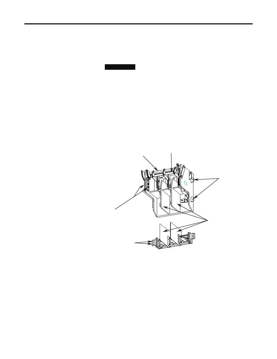
Inter-phase Barriers
Clearance Holes
Auxiliary Contacts
Dome Plugs
Shaft
Grounding Bar
Figure 2.5 – Typical Isolation Switch
Required Hardware:
– Eight (8) ¼-20 x 1.0 in. (6.3 x 1.8 x 25mm Type B) self-tapping screws
– Four (4) dome plugs (supplied)
1) Drill four (4) 0.219 in. (5.5 mm) pilot holes in the mounting surface at
Location A as shown in Figure 2.6 for the isolation switch.
2) Attach the isolation switch using four (4) ¼-20 (6.3 x 1.8 Type B)
self-tapping screws. Torque the screws according to the specifi cations
I M P O R T A N T
I M P O R T A N T