Door interlock assembly – Rockwell Automation 1503 OEM Starter Frame Components Installation Manual User Manual
Page 23
Component Installation 2-15
1503-IN050E-EN-P – June 2013
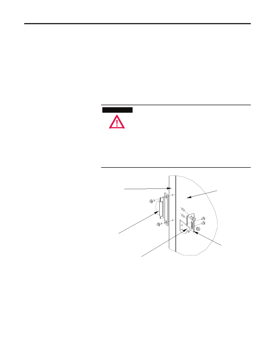
Door Interlock Assembly
When properly installed the door interlock assembly (see Figure 2.13),
used in conjunction with the isolation switch, is designed to provide the
following interlocking features:
• When the isolation switch handle is in the ON position, a pin on the
handle overlaps the Z-clip to prevent the door from being opened.
• When the door is closed and the isolation switch handle is in the ON
position, a cover catch inside the door will be held in place by the
interlock defeater lever and provide another means for holding the door
closed while the unit is energized.
The door interlock assembly must be installed for the
isolation switch handle to restrict access to the medium
voltage cell while the unit is energized. The isolation
switch handle alone will not provide safety interlocking.
If the door interlock assembly is not installed, the OEM
assumes the responsibility for providing a means to
isolate the medium voltage power cell while the unit is
energized. Failure to install a medium voltage power cell
isolation means can expose personnel to medium voltage
resulting in severe burns, injury or death.
Z-clip
Rear Door Surface
Door Flange
Cover Catch
Cover Catch
Mounting Bracket
Figure 2.14 – Door Interlock Assembly
A T T E N T I O N
A T T E N T I O N