Isolation switch ground adjustment – Rockwell Automation 1503 OEM Starter Frame Components Installation Manual User Manual
Page 41
1503-IN050E-EN-P – June 2013
Adjustments
3-7
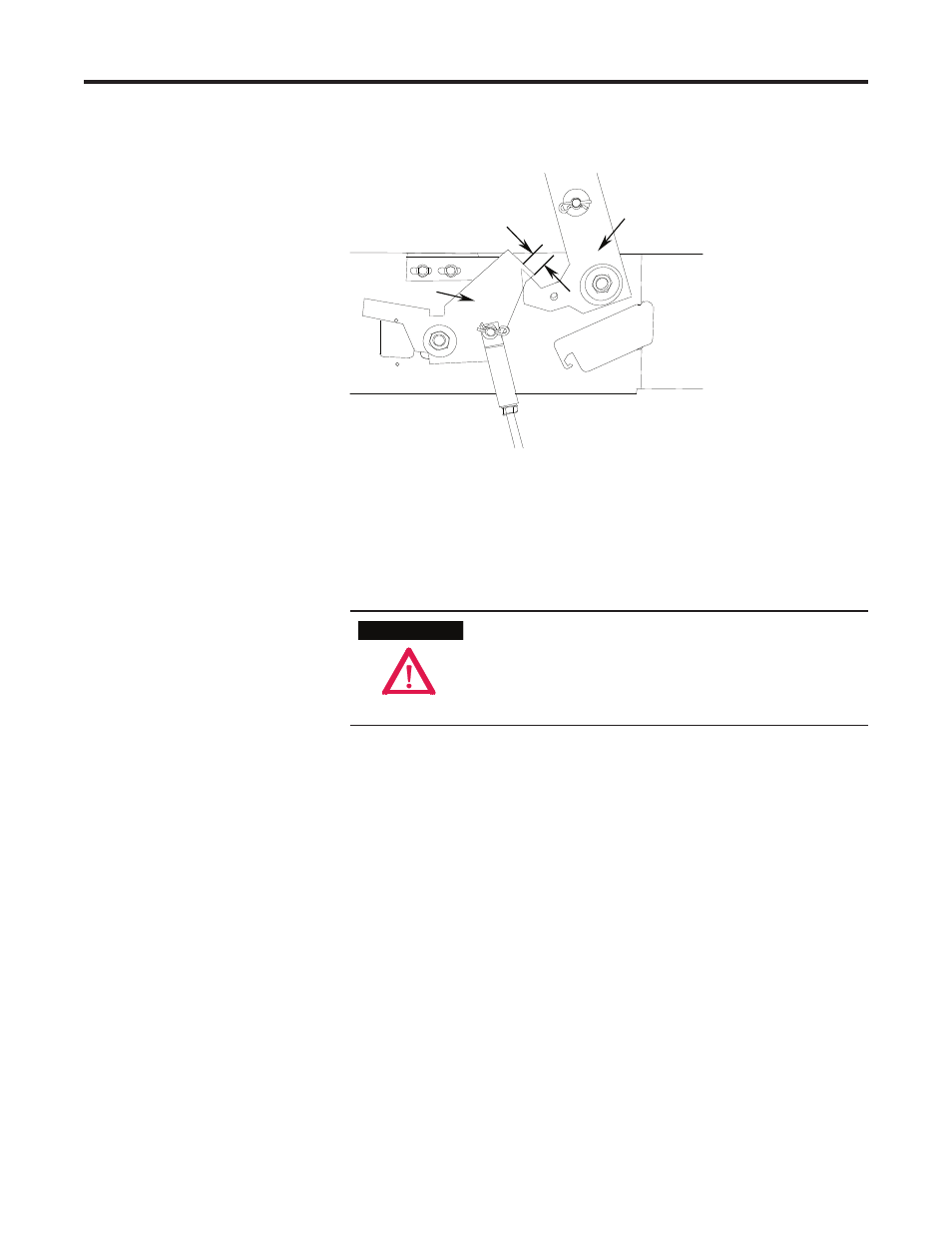
Interlock Lever
Isolation Switch
Operating Lever
Overlap 0.125 in. min.
(3 mm)
Figure 3.8 – Isolation Switch Operating Lever Overlap
14) Open the contactor. Verify that the interlock lever and the rod move
freely and that the return springs move the assembly back to the starting
position.
To avoid shock hazards, lock out incoming power before
working on the equipment. Verify with a hot stick or ap-
propriate voltage measuring device that all circuits
are voltage free. Failure to do so may result in severe
burns, injury or death.
1) Move the isolation switch handle to the OFF position.
2) Inspect the grounding of the isolation switch blades. When the isolation
switch handle is in the OFF (open) position, the isolation switch blades
must fully engage the ground pins of the ground bar. The isolation
switch blades must also be within 0.060 in. (1.5 mm) of the ground bar
when the handle is in the OFF (open) position (see Figure 3.9). When
the isolation switch handle is in the ON or closed position, the blades
must fully engage the line stabs (see Figure 3.5).
3) To adjust the distance from the blades to the bar, disconnect the
threaded connecting rod at the isolation switch operating lever (see
Figure 2.16).
4) Turn the threaded connecting rod to lengthen or shorten it. This will
adjust the position of the isolation switch blades in the ON and OFF
position.
A T T E N T I O N
A T T E N T I O N
Isolation Switch Ground
Adjustment