Additional tests, Spare parts – Rockwell Automation MV SMC Flex OEM Components User Manual
Page 52
8-4
Final Test Procedures
1503E-IN001E-EN-P – June 2013
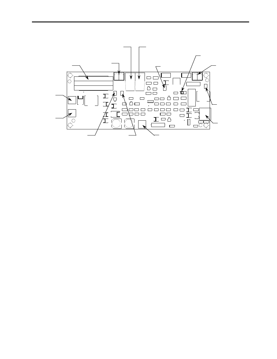
Snubber
terminal
Temperature signal
fiber-optic transmitter
Current loop CT
Plug-in test
power supply
Gate signal
fibre-optic receiver
Cathode
terminal
Common
test point
+20V test point
Overvoltage
sense terminal
+5V test point
Yellow LED
Thermistor
connector
Gate signal
test point
J2
TP1
TP2
J6
RX1
TX1
TP3
TP4
J1
J4
J3
J5
Gate/Cathode
connector
Figure 8.2 –Current Loop Gate Driver (CLGD) Board Test Points
7. Check all line and load resistances to ground at the interface board.
The measurement for all voltages should be within 11 k ohms to 13
k ohms.
Additional Tests
Perform additional tests, as outlined in Chapter 3 of User Manual,
SMC Flex Motor Controller, Bulletin 1503E, 1560E, 1562E,
Publication 1560E-UM051_-EN-P.
Spare Parts
For a complete listing of spare parts, refer to User Manual, SMC Flex
Motor Controller, Bulletin 1503E, 1560E, 1562E, Publication
1560E-UM051_-EN-P.