Power connections – Rockwell Automation MV SMC Flex OEM Components User Manual
Page 27
Power Stack Installation
4-11
1503E-IN001E-EN-P – June 2013
A T T E N T I O N
A T T E N T I O N
To avoid shock hazard, lock out incoming
power to power cables when completing
connections. Failure to do so may result in
severe burns, injury or death.
It is the responsibility of the OEM to ensure that
suitable line and load cables are used to satisfy
the requirements of the equipment and meet
local electrical codes.
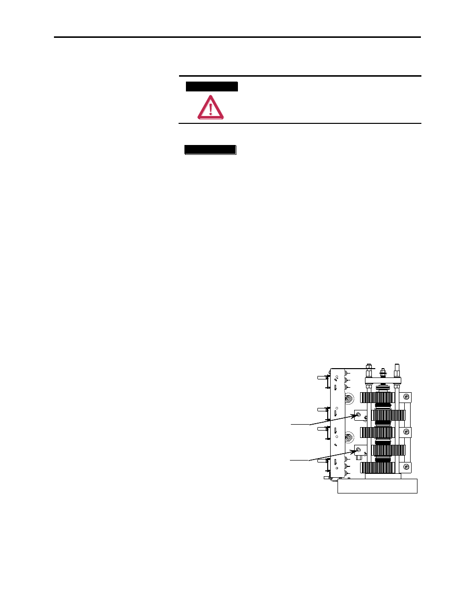
1) Use appropriate cable lugs to attach suitable line cables to the
line cable terminal (upper power terminal) of the heatsink
assembly. The terminal is predrilled with a mounting hole with a
diameter of 10.3 mm (0.406 in.). The holes are suitable for M10
(3/8 in.) hardware. Refer to Figure 4.8 for the terminal location.
Torque the fastening hardware to the specifications shown in
Table 4.D.
2) Use cable lugs to attach suitable load cables to the load cable
terminal (lower power terminal) of the heatsink assembly. Refer
to Figure 4.8 for the terminal location. Torque the fastening
hardware to the specifications shown in Table 4.D.
3) Refer to Chapters 6 and 7 for a typical wiring diagram to
determine the required connections. Appendix B includes a
typical schematic for a complete soft starter unit.
Line Cable Terminal
10.3 mm (0.406 in.) diameter
(All stacks in SMC frame have similar configuration)
Right Side View
Load Cable Terminal
10.3 mm (0.406 in.) diameter
Line Cable Terminal
10.3 mm (0.406 in.) diameter
(All stacks in SMC frame have similar configuration)
Right Side View
Load Cable Terminal
10.3 mm (0.406 in.) diameter
Figure 4.8 - Heatsink Assembly Power Connections
(4160V, 360A heatsink shown)
I M P O R T A N T
I M P O R T A N T
Power Connections