Rockwell Automation MV SMC Flex OEM Components User Manual
Page 51
Final Test Procedures
8-3
1503E-IN001E-EN-P – June 2013
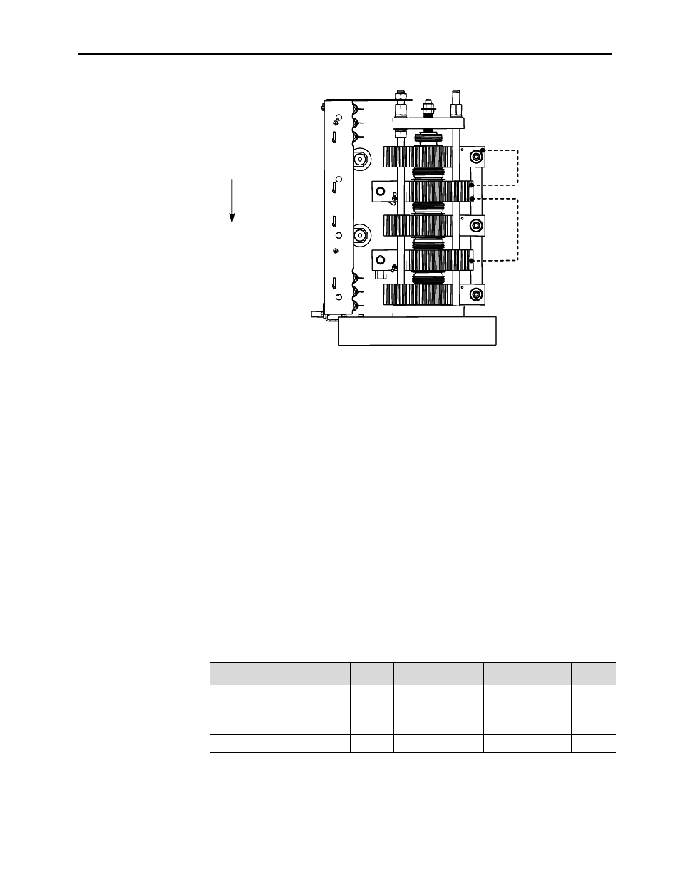
Test-jumper position
for heatsinks 1 and 2
Test-jumper position
for heatsinks 2 and 4
HS1
HS2
HS3
HS4
HS5
Heatsinks are numbered
from top to bottom.
Test-jumper position
for heatsinks 1 and 2
Test-jumper position
for heatsinks 2 and 4
HS1
HS2
HS3
HS4
HS5
Heatsinks are numbered
from top to bottom.
Figure 8.1 – Example of Jumper Positioning for Hi-pot Test - 4160V, 360A Heatsink shown
3. Measure the resistance between the line and load sides of each
phase to make sure there is zero resistance. This indicates that the
jumpers are properly set on the cathodes.
4. Perform a Hi-Pot test as required by the applicable local codes and
standards.
5. After the Hi-Pot remove the heatsink jumpers. Re-connect the six
feedback board wires.
6. Perform a resistance check for each SCR. The SCR resistance can be
checked directly at the device or at the leads on the gate driver board.
a) The gate-to-cathode resistance should range from 10 to 40
ohms for all styles.
b) The cathode-to-cathode resistance can also be checked and
compared to the results shown on Table 8.C. See Figure 8.2 for
the testing points on the gate driver boards.
Table 8.C – Power Circuit Resistance Measurements
Location of Probes
1000 V
2300 V
3300 V
4160 V
5500 V
6900 V
Cathode to Cathode (KOhms)
–
–
22-30
23-31
21-29
24-32
Cathode to Cathode (KOhms)
17-23
21-29
40-53
43-57
60-80
64-84
Cathode to Gate (Ohms)
10-40
10-40
10-40
10-40
10-40
10-40
Measured between terminals “Cathode” on CL Boards, upper two or bottom two within a phase.
Measured between terminals “Cathode” on CL Boards, top to bottom within a phase.
Measured between line and load terminals within a phase.