Anchoring, Torque requirements – Rockwell Automation MV SMC Flex OEM Components User Manual
Page 13
Power Stack Frame Installation
3-5
1503E-IN001E-EN-P – June 2013
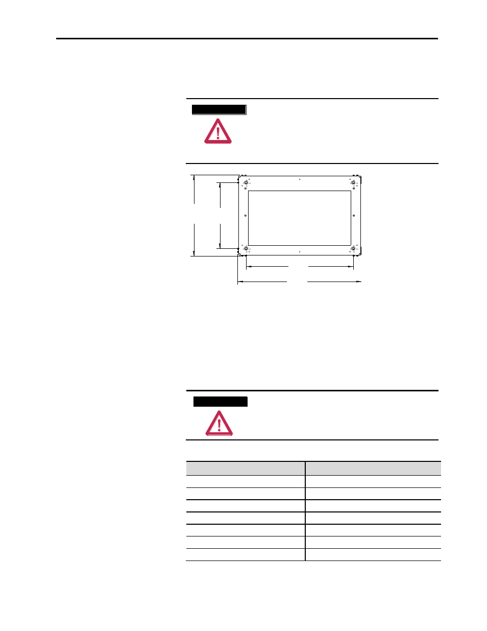
Anchoring
Mounting holes are provided in the frame and are suitable for 0.5 in.
(M12) diameter anchor bolts (refer to Figure 3.5).
A T T E N T I O N
A T T E N T I O N
The frame is designed to be anchored in the
upright position and on a level surface. Do not
attempt to mount the frame upside down or at
any angle that is not level. Improper anchoring
may cause injury to personnel and/or damage to
the equipment.
640
[25.2]
521
[20.5]
778
[30.6]
900
[35.4]
(All dimensions in millimeters [inches])
Front
Figure 3.5 – Frame Mounting Hole Locations (Bottom View)
Torque Requirements
All electrical connections must be torqued to the specifications shown
in Table 3.C.
A T T E N T I O N
A T T E N T I O N
Ensure that all electrical connections are torqued
to the correct specification. Failure to do so may
result in damage to the equipment and/or injury
to personnel.
Table 3.C – Torque Requirements
Hardware
Recommended Torque
1/4 in.
6 ft·lb (8 N·m)
5/16 in.
11 ft·lb (15 N·m)
3/8 in.
20 ft·lb (27 N·m)
1/2 in.
48 ft·lb (65 N·m)
Control Wire Terminals
2.0 – 3.3 in·lb (0.2 – 0.4 N·m)
CLGD Power Assembly Terminals
50 in·lb (5.6 N·m)
SMC Flex Control Module Terminals
5 in·lb (0.6 N·m)