Torque requirements, Power stack mounting – Rockwell Automation MV SMC Flex OEM Components User Manual
Page 20
4-4
Power Stack Installation
1503E-IN001E-EN-P – June 2013
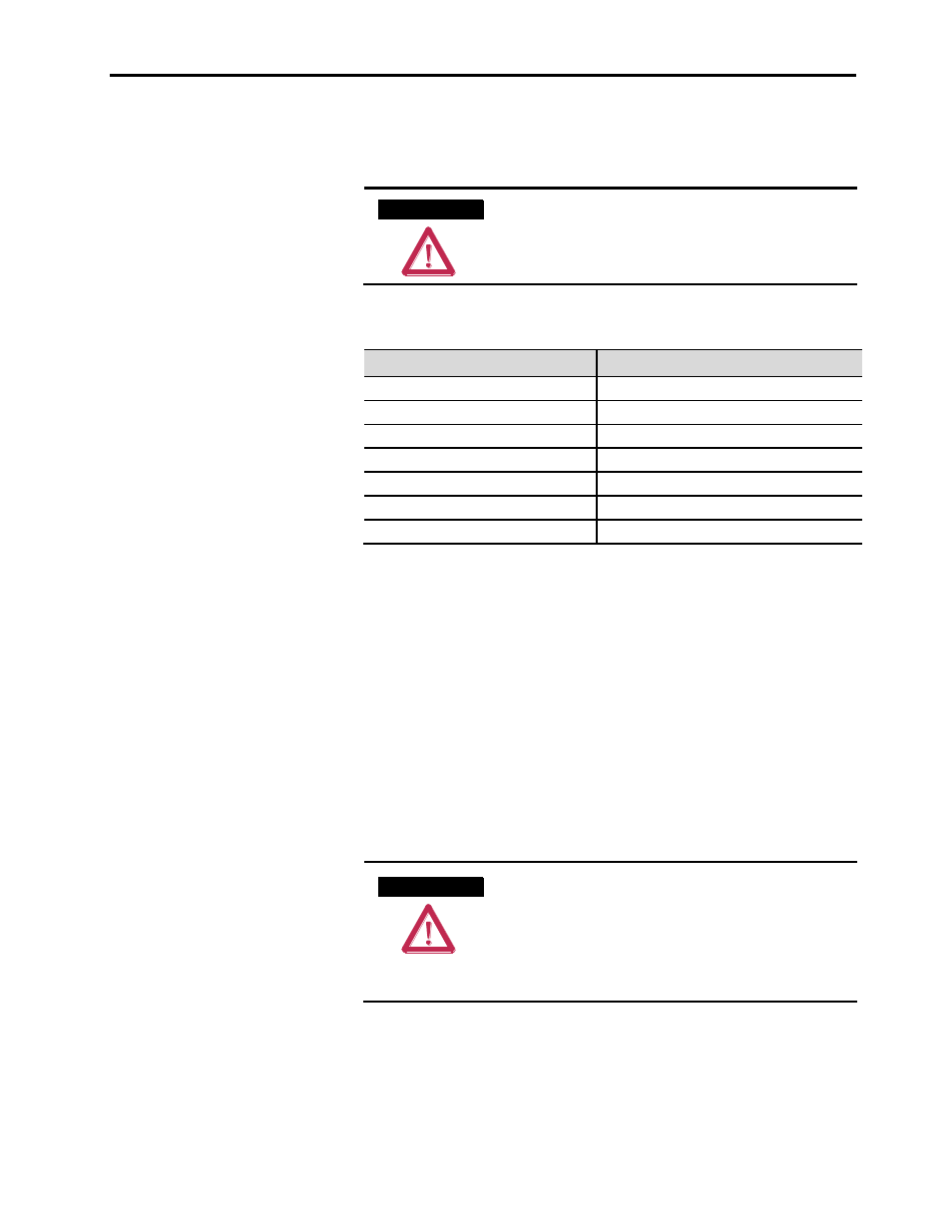
Torque Requirements
All electrical connections must be torqued to the specifications shown
in Table 4.D.
A T T E N T I O N
A T T E N T I O N
Ensure that all electrical connections are torqued
to the correct specification. Failure to do so may
result in damage to the equipment and/or injury
to personnel.
Table 4.D – Torque Requirements
Hardware
Recommended Torque
1/4 in.
6 ft·lb (8 N·m)
5/16 in.
11 ft·lb (15 N·m)
3/8 in.
20 ft·lb (27 N·m)
1/2 in.
48 ft·lb (65 N·m)
Control Wire Terminals
2.0 – 3.3 in·lb (0.2 – 0.4 N·m)
CLGD Power Assembly Terminals
50 in·lb (5.6 N·m)
SMC Flex Control Module Terminals
5 in·lb (0.6 N·m)
Power Stack Mounting
Power stacks are to be mounted in a vertical orientation in order to
provide adequate component cooling. Mount the heatsink in a
suitable location using the mounting holes provided in the assembly.
Use M10 (3/8”) or similar hardware for the mounting hole dimensions
of 10.7 mm x 15.9 mm (0.421in. x 0.625 inches).
Power stacks rated 180/360A, up to 4799V, are provided with
mounting brackets (as shown in Figures 4.2 and 4.4). The mounting
brackets should be affixed to a horizontal surface, and the power stacks
slide into and bolt to the mounting brackets.
A T T E N T I O N
A T T E N T I O N
Maintain sufficient clearance between the power
phases and between phases and grounded
surfaces. Refer to local electrical codes to
determine the required clearance. Failure to do
so may result in injury to personnel or damage to
the equipment.