Original instructions, Product description, Special features – Rockwell Automation 440L GuardShield PAC Type 4 Safety Light Curtain User Manual
Page 7: Guardshield light curtain principle of operation
GuardShield™ PAC Safety Light Curtain Installation Instructions
5
Original instructions
• The national/international rules and regulations apply to
the installation, use and periodic technical inspections of
the safety light curtain, in particular:
♦
Machine Directive 98/37/EEC
♦
Equipment Usage Directive 89/655/EEC
♦
The work safety regulations/safety rules
♦
Other relevant health and safety regulations
Manufacturers and users of the machine with which the
safety light curtain is used are responsible for obtaining and
observing all applicable safety regulations and rules.
• The notices, in particular the test regulations of these
installation instructions (e.g. on use, mounting, installation
or integration into the existing machine controller) must be
observed.
• The tests must be carried out by specialist personnel or
specially qualified and authorized personnel and must be
recorded and documented to ensure that the tests can be
reconstructed and retraced at any time.
• The installation instructions must be made available to the
user of the machine where the GuardShield PAC safety light
curtain is installed. The machine operator is to be instructed
in the use of the device by specialist personnel and must be
instructed to read the installation instructions.
Product Description
This section provides information on the special features and
properties of the safety light curtain. It describes the structure
and functions of the unit, in particular the different operating
modes.
® Please read this section before mounting, installing and
commissioning the unit.
Special Features
• Start interlock
• Restart interlock
• External Device Monitoring (EDM)
• Machine test signal
• Beam coding
GuardShield Light Curtain
Principle of Operation
The GuardShield PAC safety light curtain consists of a
nonmatched pair of optic units, i.e. transmitter and receiver with
the same number of beams and spacings. The transmitter and
receiver operate on +24V DC. The maximum distance between
the transmitter and receiver is referred to as the protective field
width or range. The protective field height is the distance
between the first beam and the last beam in the device.
The transmitter emits sequential pulses of infrared light, which
are received and processed by the GuardShield PAC receiver. The
synchronization of the timing of the emission and reception of
infrared light pulses is accomplished optically by the first beam
adjacent to the GuardShield PAC’s status LEDs. This beam is
referred to as the synchronization beam. Because the GuardShield
PAC’s transmitter and receiver are optically synchronized, no
electrical connection is required between the transmitter and
receiver.
The GuardShield PAC’s receiver has two safety outputs, OSSDs
(Output Signal Switching Devices) and one nonsafety auxiliary
output. When the GuardShield PAC’s transmitter and receiver are
properly powered and aligned, all OSSDs are current sourcing
+24V DC with a switching capacity of 500mA. The two safety
OSSDs are cross monitored and short-circuit protected.
Interruption of the sensing field causes the Receiver to switch the
sourced current Off (0V DC).
Restoring the GuardShield PAC’s sensing field, (in Guard only
configuration) causes all outputs (OSSDs) to switch to the active
high state (resume current sourcing +24V DC with a switching
capacity of 500mA).
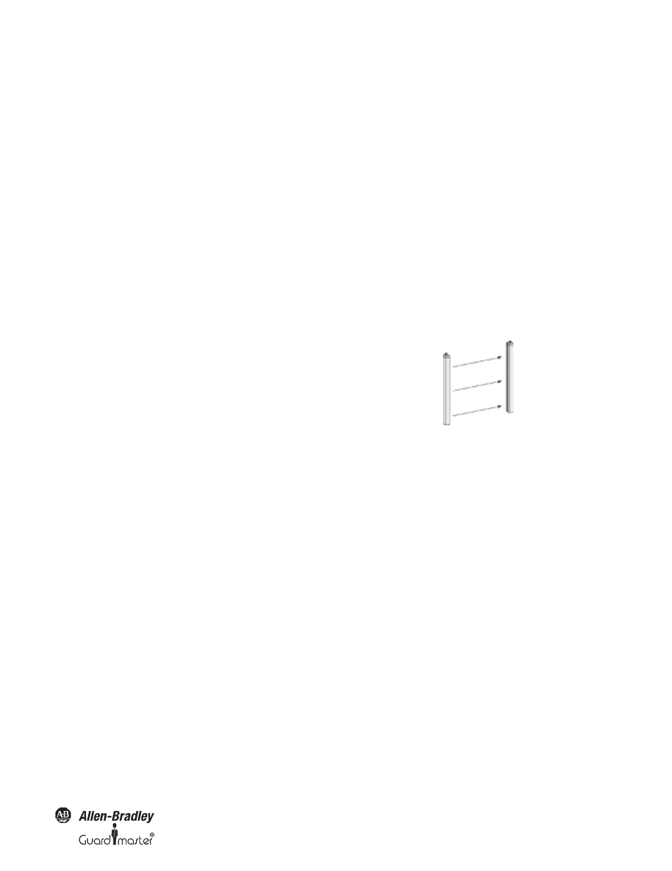
The GuardShield PAC Light Curtain
The GuardShield PAC safety light curtain consists of a transmitter
and a receiver.
Figure 1: Components of the GuardShield PAC
The individual beams of the GuardShield PAC are identified by
markings on the housings.
The width of the protective field is derived from the length of the
light path between sender and receiver and must not exceed the
maximum rated width of the protective field 16 m (52.5 ft).
The GuardShield PAC is also offered with an integrated laser
alignment system which has a constantly powered Class 1, eye
safe laser located in the top of the GuardShield PAC transmitter
and in the bottom of the GuardShield PAC receiver. Each Class 1,
eye safe laser emits a low level of visible light. Simply blocking this
light below the finger symbol causes the light to be reflected back
to a photo sensor which changes the condition of the laser light. If
this light is at a low level, interrupting it will cause the laser to emit
a highly visible level of light. Interrupting the visible light in the
same location will cause the laser to switch to a low level of
emission. The emission of visible light will also change to a low
level after five minutes of activation.
Across from each laser is a target used to help with the alignment
of the GuardShield PAC pair. Positioning the visible light in the
center of the top and bottom targets will position the
GuardShield PAC pair for optimal alignment.
Transmitter
Receiver