Original instructions, Edm connection, Connections [mm (in.) – Rockwell Automation 440L GuardShield PAC Type 4 Safety Light Curtain User Manual
Page 16
GuardShield™ PAC Safety Light Curtain Installation Instructions
14
Original instructions
EDM Connection
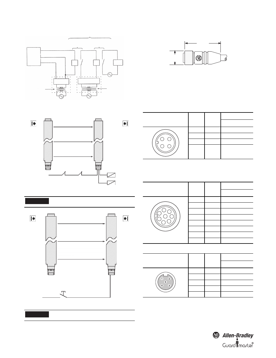
Figure 9: Connecting the contact elements to the EDM
Figure 10: Connecting the reset button/restart button
Hazardous
voltage level
Hazardous
voltage level
Hazardous voltage level
Motor, etc.
Basic Insulation
Basic Insulation
0V (blue)
+24V (brown)
Re-inforced
insulation or
double insulation
Guard
Shield
Output (pink
and grey)
Basic Insulation (see
note)
Double Insulation
Power
Supply Unit 2
Unit 1
K1
K1
K2
K2
Contactor
Coils
k2
k1
k2
Contacts
k1
Contacts
6
Transmitter
Receiver
24V
Pin 4
5
IMPORTANT
Not available for GuardShield PAC with
ArmorBlock Guard I/O connectivity.
Reset/restart button
Pin 8
24V
Transmitter
Receiver
24V
IMPORTANT
Not available for GuardShield PAC with
ArmorBlock Guard I/O connectivity.
Connections [mm (in.)]
Cables/Connectors
The GuardShield PAC transmitter connector is a four-pin DC micro
connector offered in cable lengths from 2 to 30 meters. The
GuardShield PAC receiver connector is an 8-pin DC micro
connector offered in cable lengths of 2 to 30 meters.
GuardShield PAC Standard and GuardShield PAC with
ArmorBlock Guard I/O Connectivity
Note: The transmitter is not expected to be connected to the
ArmorBlock Guard I/O module.
Standard GuardShield PAC Receiver Connector
GuardShield PAC Receiver Connector for ArmorBlock Guard I/O Connectivity
Transmitter Connection
Face View of
Female DC Micro
Color
Pin No.
Signal
Transmitter
Brown
1
+24V DC
White
2
No Connection
Blue
3
0V DC
Black
4
Machine Test Signal
Receiver Connection
Face View of
Female DC Micro
Color
Pin No.
Signal
Receiver
White
1
Auxiliary Output
Brown
2
+24V DC
Green
3
Ground
Yellow
4
EDM
Grey
5
OSSD 1
Pink
6
OSSD 2
Blue
7
0V DC
Red
8
Start/Restart
Top View
Color
Pin No.
Signal
Receiver
Brown
1
+24V
White
2
OSSD 2
Blue
3
0V
Black
4
OSSD 1
Grey
5
NC
15
(0.57)
42 (1.7)
1
4
3
2
2
1
5
8
7
6
4
3