Original instructions, Multiple guardshield pacs, Mounting brackets – Rockwell Automation 440L GuardShield PAC Type 4 Safety Light Curtain User Manual
Page 14
GuardShield™ PAC Safety Light Curtain Installation Instructions
12
Original instructions
The standard GuardShield PAC has an LED in the receiver which is
used as an alignment aid. This LED will begin flashing when the
infrared light from the transmitter is “seen” by the receiver. This
LED turns off when optimal alignment is attained. An external
laser (440L-ALAT) and mounting bracket (440L-AF6109) is offered
as an accessory for aligning the GuardShield PAC.
Alignment Procedure: Standard GuardShield PAC
Mount and connect both transmitter and receiver. They must be
parallel to each other and be positioned at the same height.
Turn on power to GuardShield PAC system.
Rotate the Transmitter while watching the amber LED on the
receiver to find the point where the indicator for the ON state
(Green LED) illuminates and the amber LED goes off.
Determine the maximum left and right turning angles and
position unit in center. Tighten all hardware assuring that the
alignment indicator is not illuminated.
Cycle power to assure that the system powers up and goes to the
ON state (alignment indicator is OFF)
The GuardShield PAC meets the requirements of IEC 61496 which
requires that the optics of the transmitter and receiver emit and
receive infrared light at a maximum of +/-2.5°. This requirement
creates a tight optical path of infrared light and as such may make
the GuardShield PAC somewhat difficult to align at maximum
range or when corner mirrors are being used in the application to
provide two or three sided perimeter guarding.
When using the GuardShield PAC in perimeter guarding
applications, particularly with corner mirrors, it is best to use the
Allen Bradley GuardMaster laser alignment tool to ease the
alignment process. The laser alignment tool part number is 440L-
ALAT. It is also necessary to use the GuardShield mounting
bracket (440L-AF6109) to mount the laser alignment tool to the
GuardShield PAC housing
The GuardShield PAC is also offered with an integrated laser
alignment system. Select the appropriate cat. nos. for this model
of GuardShield PAC.
Alignment Procedure for GuardShield PAC
with Integrated Laser Alignment
1. Properly locate the GuardShield PAC pair from the point of
operation hazard after performing the safety distance
calculation.
2. Using the GuardShield PAC mounting brackets, mount the
transmitter and receiver so that they are facing one another
and are positioned in the same direction. A reference would be
that the indicator LEDs are opposite one another.
3. Turn on each laser by placing a finger or hand in front of each
laser.
4. Adjust the transmitter and receiver in such a way that both
visible laser beams hit the laser targets opposite each laser. A
small deviation from the center of the target is allowable.
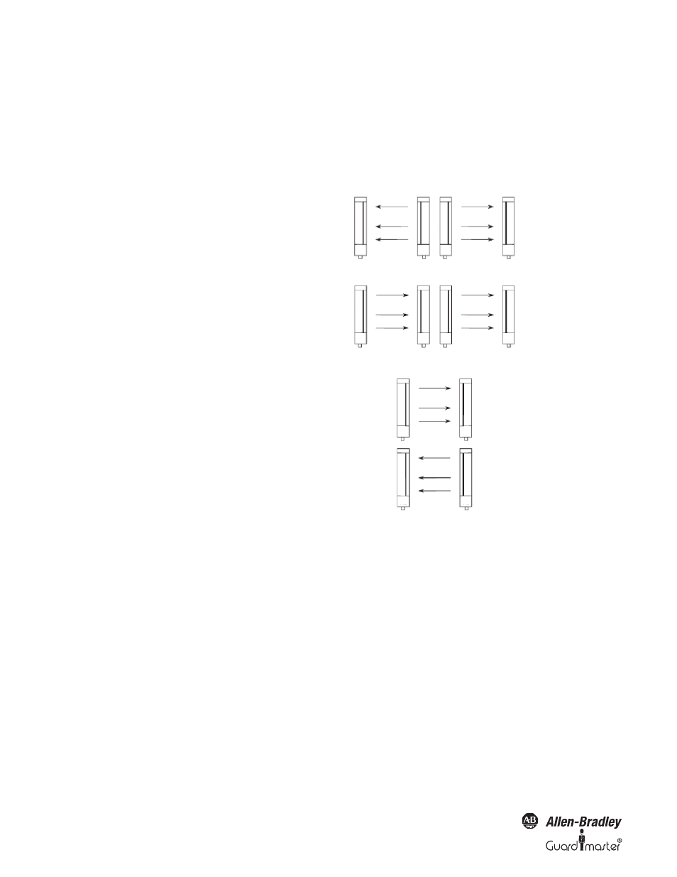
Multiple GuardShield PACs
When two or more GuardShield PACs are mounted in close
proximity to one another, it may be possible for the receiver of
one GuardShield PAC pair to receive infrared light from the
transmitter of another GuardShield PAC pair. This optical
interference can be over come by the GuardShield PAC feature of
Beam Coding. Beam coding changes the pulse pattern of infrared
light emitted by a GuardShield PAC transmitter.
Figure 5: Multiple GuardShield PAC alignment options
Mounting Brackets
The GuardShield PAC is mounted using right angle brackets
attached to the endcaps of both transmitter and receiver. Each
GuardShield PAC is supplied with standard right angle mounting
brackets and self-threading screws. It may be necessary to use
additional brackets to mount the GuardShield PAC at a proper
safety distance from the machinery hazard.
Transmitters emit in opposite direction.
Each receiver receives only the beams of
the appropriate transmitter.
Transmitters emit in same direction:
➡Coding necessary
Positioning of the light curtain:
Transmitters emit in opposite direction.
Noncoded
Coded