Installation 8, 3 installation instructions – Rockwell Automation 836E Solid-State Pressure Sensors User Manual
Page 8
Installation
8
3. 3
Installation Instructions
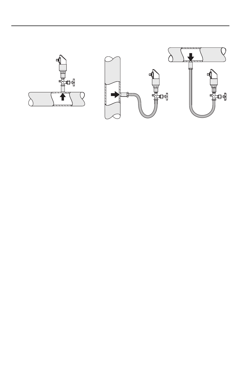
Fig. 3: Typical applications of the Bulletin 836E to measure pressure in gases, steam and liquids.
➀
Bulletin 836E pressure switch
➁
Shut-off assembly
➂
U-pipe
For typical applications of the Bulletin 836E, see Figure 3 above:
• The image on the left illustrates how the 836E should be applied for pressure measurement in
gases. The switch should be mounted with a shut-off assembly above the sampling nozzle so
that any condensate can drain off into the process.
• The center image shows the correct installation for pressure measurement in steam. Note how
the Bulletin 836E is mounted with a U-pipe below the sampling nozzle. Fill the U-pipe with fill
fluid before commissioning.
• For pressure measurement in liquids, see the drawing on the right of Figure 3 above. The
Bulletin 836E should be mounted below or at the same level as the sampling nozzle.
Additional considerations:
• Do not mount the device in the product flow or at a point where it could be affected by
pressure pulses.
• Calibration and testing are easier if the device is mounted downstream of a shut-off assembly.
• The orientation of the Bulletin 836E can result in zero point shift, i.e. the measured value does
not display zero in a non-pressurized state. This zero point shift can be corrected (see Section 4
– Operation).
• The digital display can be electronically rotated 180° (see Section 4 – Operation).
• The housing can be rotated up to 310° for optimal readability and ease of wiring.
➀
➁
➂
➂
➀
➁
➀
➁
Gas
Steam
Liquid