Installation 7, 2 process connection – Rockwell Automation 836E Solid-State Pressure Sensors User Manual
Page 7
Installation
7
3. 2
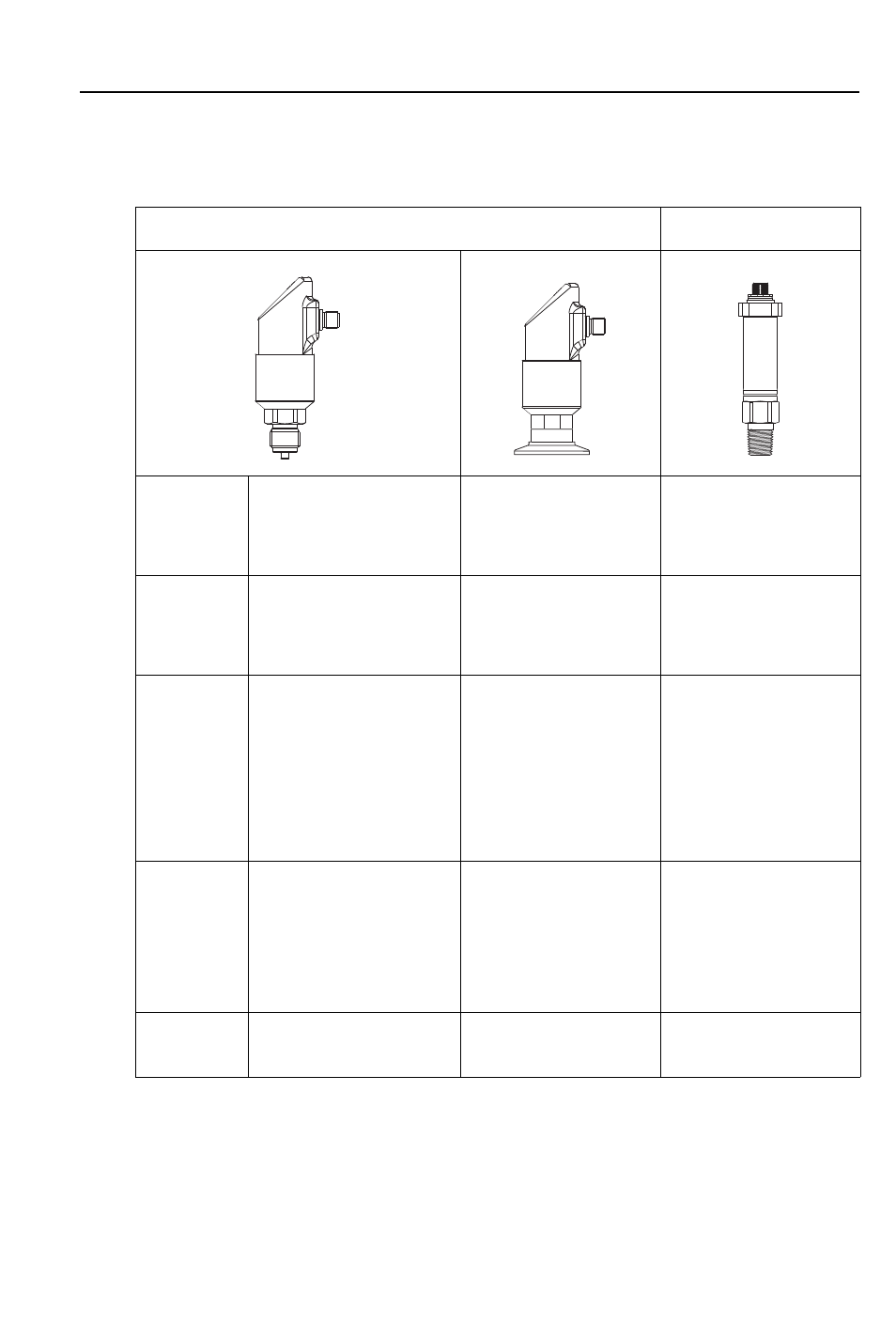
Process Connection
The following table outlines the characteristics of the Bulletin 836E, its process, and sanitary
connections.
Notes:
➀
Male adapters cannot be used with the 0…1450 psi or the 0…6000 psi display models
➁
For conversion of psi to other units (bar, kPa, etc.), refer to inside back cover of this document
836E Pressure Switch
836E Nondisplay
Measuring
cell
Piezoresistive measuring
cell and metallic measuring
diaphragm
With piezoresistive meas-
uring cell and metallic
measuring diaphragm for
sanitary applications
Piezoresistive measuring
cell and metallic measur-
ing diaphragm
Application
Measurement and monitor-
ing of absolute and gauge
pressures
Measurement and moni-
toring of absolute and
gauge pressures in sani-
tary applications
Measurement and moni-
toring of absolute and
gauge pressures
Process
connection
➀
Thread
− 1/4 NPT female
− 1/4 NPT male
− G 1/4 BSPP female
− G 1/4 BSPP male
− SAE 7/16…20 UNF
female
− SAE 7/16…20 UNF
male
Sanitary
− Clamp 1…1½ in.
− Clamp 2 in.
Thread
– 1/2 NPT male
– 1/4 NPT male
– 1/2 NPT male
1/4 NPT female
– G 1/2 male
– G 1/4 male
Measuring
range
➁
-14.5…+14.5 psi
(-1…1 bar)
0…58psi (0…4 bar)
0…145 psi (0…10 bar)
0…580 psi (0…40 bar)
0…1450 psi (0…100 bar)
0…6000 psi (0…400 bar)
0…1 bar/15 psi
to
0…40 bar/600 psi
0…15 psi (0…1 bar)
0…50 psi (0…3 bar)
0…150 psi (0…10 bar)
0…500 psi (0…34 bar)
0…1500 psi (0…103 bar)
0…6000 psi (0…413 bar)
Process
temperature
−40...+100 °C
(−40...+212 °F)
−40...+100 °C
(135 °C max. 1 hour)
–25…+70 °C
(–13…158 °F)