Solid ground systems, Non-solid ground systems, A-12 a-12 – Rockwell Automation 20G PowerFlex SCR Bus Supply User Manual
Page 54
A-12
Specifications
PowerFlex SCR Bus Supply User Manual
Publication 20S-UM001G-EN-P
Solid Ground Systems
Using the hole location dimensions from
, install the HF filter
using the four (4) M4 x 20 screws through the four holes in the plastic body
of the HF filter (
). Then install the three (3) M4 x 8 screws
through the PE grounding plate. Do NOT use the nylon standoffs.
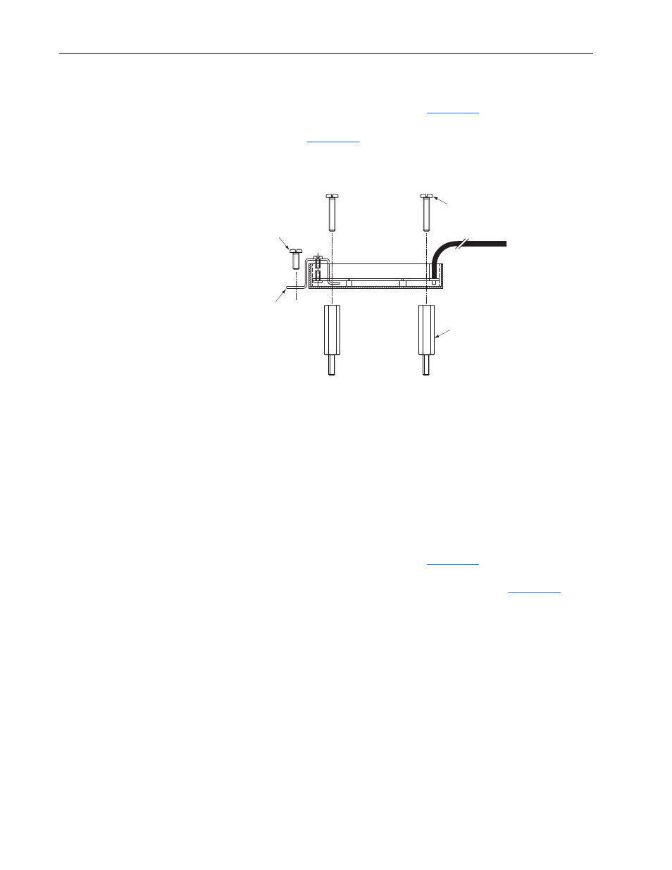
Figure A.7
Mounting the HF Filter
Non-Solid Ground Systems
The HF filter may be installed with floating or HRG ground systems for
line-to-line transient protection. In this type of installation, the PE
grounding plate should NOT be connected to ground, but remain isolated
from ground.
Important: The HF filter PE grounding plate will be floating with potential
high voltage with respect to earth ground when AC line power
is applied.
Using the hole location dimensions from
, install the HF filter
using the four (4) M4 x 19 nylon standoffs and four (4) M4 x 20 screws
through the four holes in the plastic body of the HF filter (
).
Finger tighten the nylon standoffs.
Do NOT install the three (3) M4 x 8
screws through the PE grounding plate.
Install the High Voltage Warning label onto the PE grounding plate when
the HF filter is installed with a floating or HRG ground system.
M4 x 8
3 Places
(for solid ground
system only)
M4 x 20
4 Places
PE
Grounding
Plate
M4 x 19
Nylon Standoffs
4 Places
(for floating or
HGR system only)