Drive run interlock, Control wiring example, Jumper settings – Rockwell Automation 20G PowerFlex SCR Bus Supply User Manual
Page 26: Jumper settings -12
1-12
Installation/Wiring
PowerFlex SCR Bus Supply User Manual
Publication 20S-UM001G-EN-P
Drive Run Interlock
To protect the Bus Supply from overtemperature, the normally closed
contacts (Bus Supply Overtemperature - terminals 10 and 11) should be
wired to either the AC line input contactor for the Bus Supply or the Run
interlock circuit (enable input) of each connected drive. This ensures that
the drives are stopped in case of Bus Supply Overtemperature.
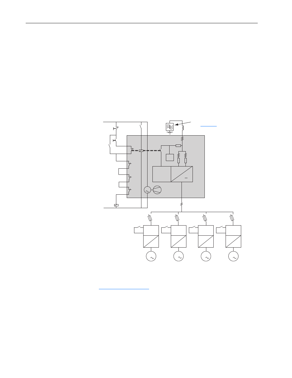
Control Wiring Example
Figure 1.8
Example of SCR Bus Supply, 1000A Single with Multiple Drives Using
Drive Run Interlocks, Running Simultaneous
Jumper Settings
The PowerFlex SCR Bus Supply precharge board has three jumpers. See
Figure 1.9 on page 1-13
for jumper locations and positions.
• LINE TYPE Jumper: Always set to the “3-ph” default right-side position
(towards the board edge).
• SPARE 1 Jumper: For board firmware version 1.21 (or earlier), this
jumper is non-functional. For firmware version 1.22 (or later), the SCR
Bus Supply is shipped with this jumper in the right (default) inactive
state position. When the jumper is placed in the left (RGU/AFE) or
active position, the firmware is active for SCR and RGU/AFE
parallel
operation on common bus systems, where the SCR is in parallel with an
DC Bus
10
115 VAC
6
8
9
11
7
2
1
f
4
5
PowerFlex
SCR Bus
Supply
F7-11
F7-F9
F1-F6
F1-6
L1
K1M
K1M
K1M
K1M
K1M
K1M
K1M
Run
Stop
K1 *
M
0
*
115
* The customer’s controls
must, at a minimum,
command the blower
to run whenever contactor
K1 is enabled.
RC
-
f
-
f
-
f
-
AC Drive
110 kW
205A
AC Drive
110 kW
205A
AC Drive
110 kW
205A
AC Drive
45 kW
85A
f
M
Precharge
Board
>°C
3
M
3
M
3
M
3
NOTE: Optional HF Filter
(see
)