Rockwell Automation 20G PowerFlex SCR Bus Supply User Manual
Page 23
Installation/Wiring
1-9
PowerFlex SCR Bus Supply User Manual
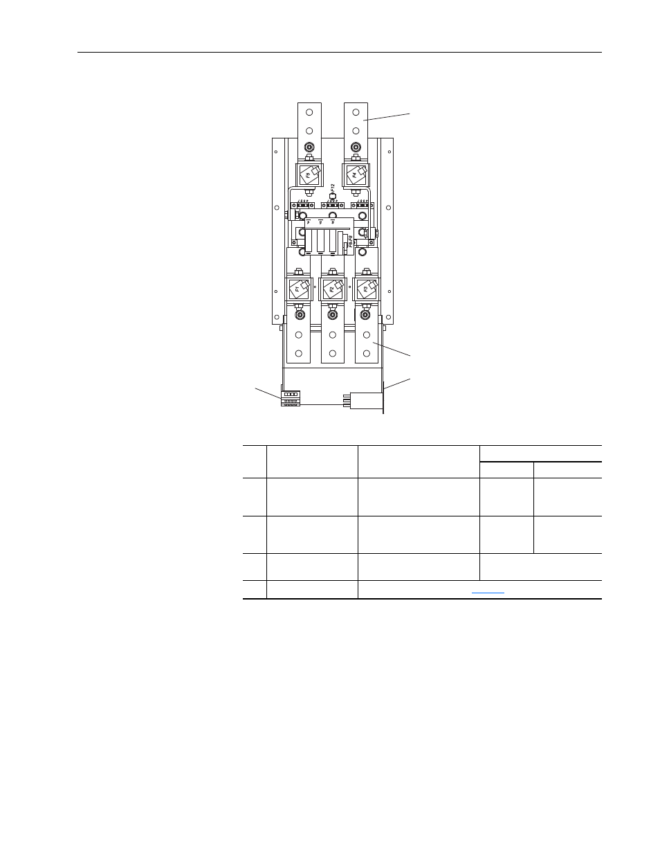
Figure 1.5
600A Unit Bus Bar and Terminal Locations for Customer Wiring
Table 1.D 600A Unit Power Connection Specifications
Item Description
Copper Bus Bars
(1)
(1)
Input/output power bus bar connections require the use of either lug type connectors to terminate field-installed
conductors or bus bars.
Recommended Minimum Size
Bus Bar
Wire
➊
AC Line Input
L1, L2, L3
50 x 5 mm (1.97 x 0.2 in.) with
two 14 mm (0.55 in.) diameter
holes for customer terminal
50 x 5 mm
240 mm
2
(or 2 x 95 mm
2
)
➋
DC Bus
DC+, DC-
50 x 5 mm (1.97 x 0.2 in.) with
two 14 mm (0.55 in.) diameter
holes for customer terminal
60 x 5 mm
300 mm
2
(or 2 x 120 mm
2
)
➌
Protective Earth PE
M12 x 25 mm (0.98 in.) stud;
torque to 15 N•m (133 lb•in)
Size per NEC or local code
➍
Control Terminal Block
DC+
DC-
➋
L1
L2
L3
➊
➍
➌