Control synchronization cable, Control synchronization cable -36 – Rockwell Automation 20L PowerFlex 700L Liquid-Cooled Adjustable Frequency AC Drive User Manual
Page 84
3-36
Frame 3A and 3B Installation
PowerFlex 700L Frames 2, 3A, and 3B Liquid-Cooled AC Drives User Manual
Publication 20L-UM001E-EN-P
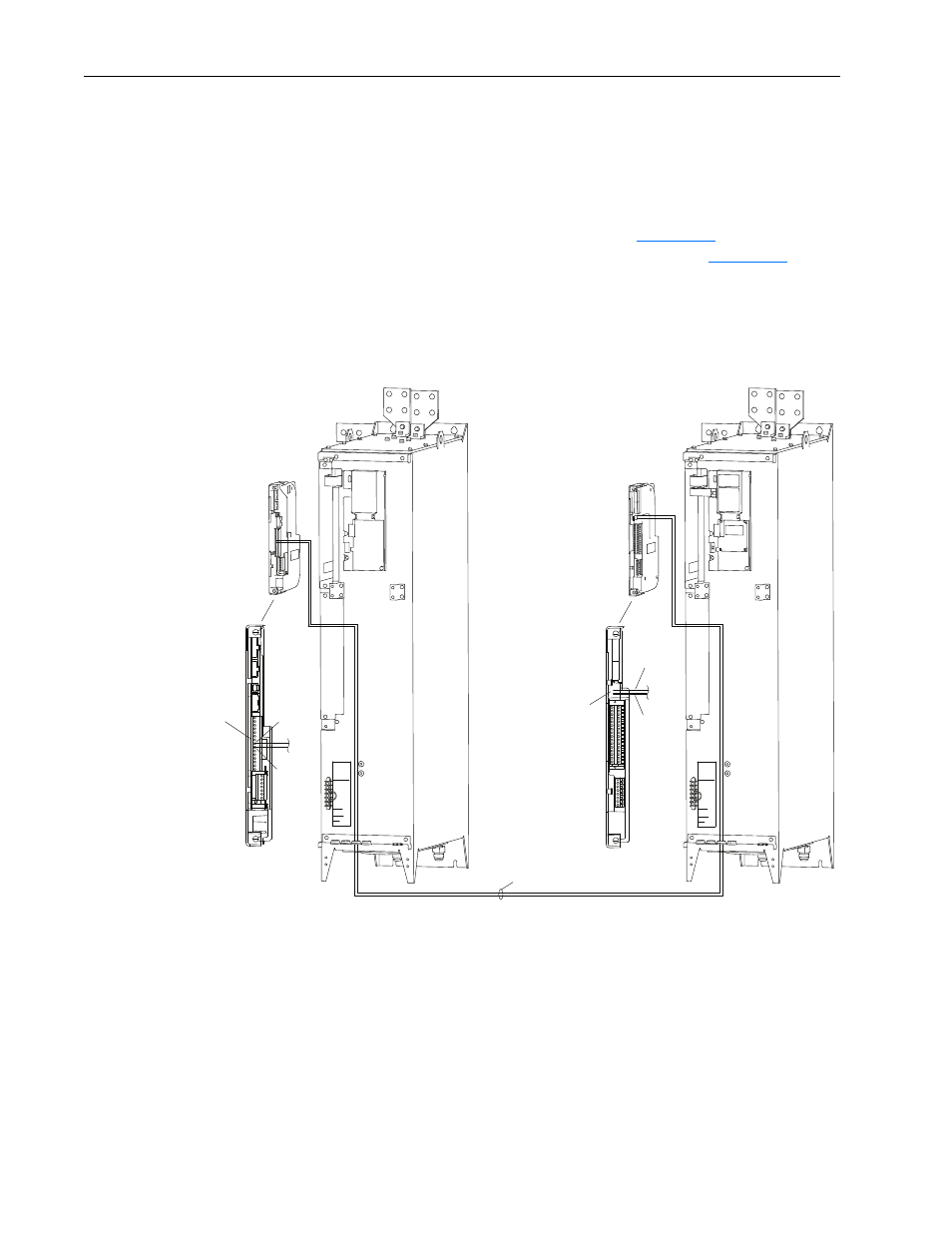
Control Synchronization Cable
To enable synchronization between the Inverter control board and the
Converter control board, you must connect a synchronization cable to each
board. The connection method is different for PowerFlex 700L drives with
700 Vector Control than for 700S Phase II Control. The 700 Vector Control
synchronization cable connection is shown in
Figure 3.33
. The 700S Phase
II Control synchronization cable connection is shown in
Figure 3.34
. The
appropriate version of the cable is provided in a plastic bag with each
Inverter Power Module. Only one Inverter Power Module may be coupled to
a Converter Power Module.
Figure 3.33 Frame 3B 700 Vector Control Synchronization Cable Connection
1
15
P1 Terminal Block for
Control Synchronization
Cable Connection
TB2 Header for
Control Synchronization
Cable Connection
Control Synchronization Cable
(Factory-Provided)
Active Converter Power Module
Inverter Power Module
P1-7
TB2-2
TB2-1
P1-8
Active Converter
Control Cassette
700 Vector
Control Cassette
24 VDC
DC POSITIVE
DC NEGATIVE
1 120 VAC
2 PRECHARGE COIL
6 INDUCTOR OVERTEMP
WIRE RANGE:
24-10 AWG
(0.2-4 MM)
4 CHARGE FEEDBACK
GATE ENABLE
STRIP LENGTH:
0.31 IN (8 MM)
TORQUE:
8 IN-LB
(0.9 N-M)
24 VDC
DC POSITIVE
DC NEGATIVE
1 120 VAC
2 PRECHARGE COIL
6 INDUCTOR OVERTEMP
WIRE RANGE:
24-10 AWG
(0.2-4 MM)
4 CHARGE FEEDBACK
GATE ENABLE
STRIP LENGTH:
0.31 IN (8 MM)
TORQUE:
8 IN-LB
(0.9 N-M)