Rockwell Automation 20L PowerFlex 700L Liquid-Cooled Adjustable Frequency AC Drive User Manual
Page 145
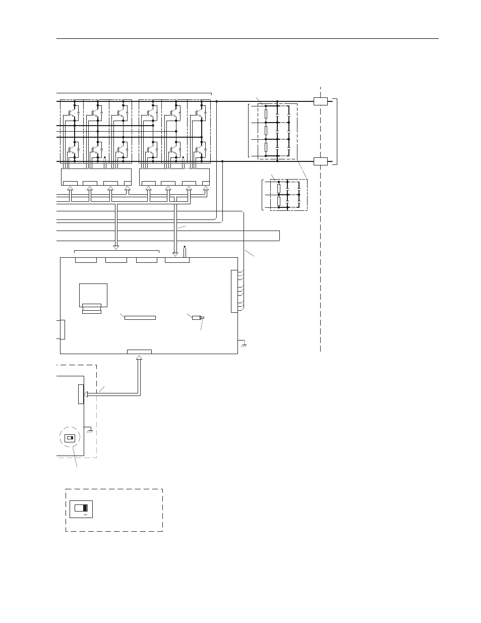
Frame 3A and 3B Schematics
C-15
PowerFlex 700L Frames 2, 3A, and 3B Liquid-Cooled AC Drives User Manual
J1
IGBT Interface PCB
IGBT Interface PCB
J9
J6
L3 Gate
L2 Gate
J5
J1
J2
J3
J4
J1
NTC
J4
L1 Gate
J1
J2
J3
J4
J7
Current
Feedback
Converter IGBT Modules Option
For 600V and
690V Classes
For 400V and
480V Classes
DC (-)
DC (+)
C
C
C
C
C
C
40-Pin
MCB Cable
Chillplate NTC
J8
R3
R2
R1
SW1
See DETAIL A
SW1
DETAIL A
ON <
DPI Peripheral = OFF (See Note 5-A)
DPI Master = ON (See Note 5-B)
C
C
R1
R2
C
C
2
1
2
1
2
1
2
1
2
1
NOTES:
1.) MOV's must be installed in the input filter section of the drive.
2.) Corner grounding is:
A. Permitted for 400V, 480V, and 600V Classes.
B. Not permitted for 690V Class.
3.) Jumper J3-9, 10 is provided with Addressable Power PCB.
4.) Product software supports only one external HIM. Do not connect
external HIM if one is also connected to the Inverter Power Module.
A splitter box is required for multiple external HIM devices.
5.) DPI Cable and SW1 Options:
A. Use with Active Converter Power Module (Catalog String position 13 = G).
B. Use with Active Converter Power Module - Stand Alone (Catalog String position 13 = P).
N
T
C
N
T
C
#3 - Upper Middle
#4 - Top
DC Bus
Harness
To Power
Supply PCB
J3
DC Bus
Harness
To Power
Supply PCB
J2
Temp. Sense Harness
DC Output
to Inverter
Power Module
J11
J5
Addressable Power PCB
Converter
Rating Plug
PCB Option
28-Pin
Board-to-Board
16-Pin
Board-to-Board
J2
J3
Jumper J3-9,10 always used.
See Note 3.
Current Harness