C-14 – Rockwell Automation 20L PowerFlex 700L Liquid-Cooled Adjustable Frequency AC Drive User Manual
Page 144
C-14
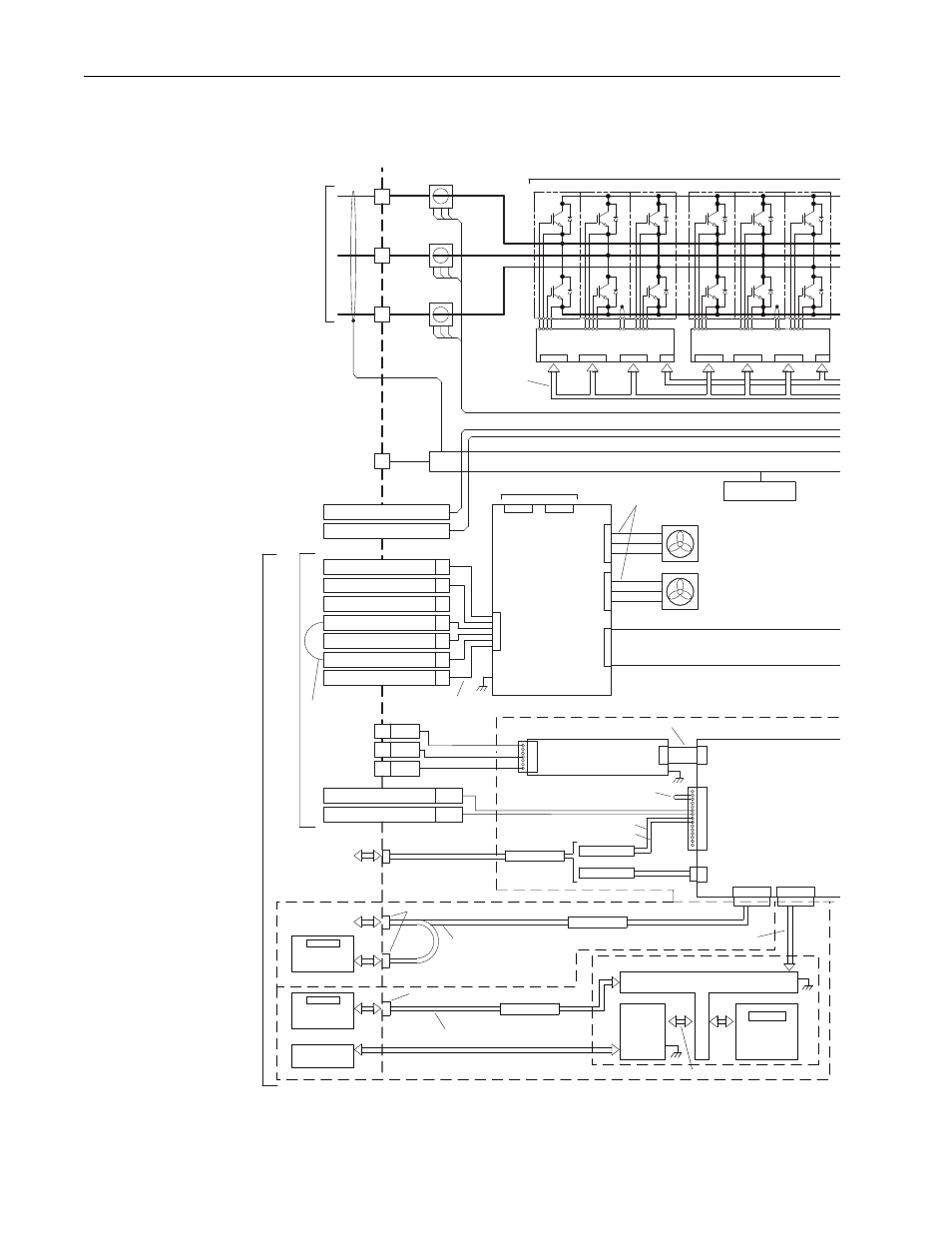
Frame 3A and 3B Schematics
PowerFlex 700L Frames 2, 3A, and 3B Liquid-Cooled AC Drives User Manual
Publication 20L-UM001E-EN-P
Frame 3B Active Converter Power Module Schematic – 400/690V, 3 Phase
IGBT Interface PCB
IGBT Interface PCB
Gate Enable
Inductor Overtemp
Precharge Feedback
Precharge Coil
DC(-) Testpoint
DC(+) Testpoint
24V
PE
J6
J4
J1
Chassis
TB5
J1
Control Cassette
J1
I/O Shield Bus
J2
J3
J4
J2
J4
J3
CT3
CT2
L3
L2
Converter IGBT Modules Option
CT1
L1
J2
J8
J1
P2
P1
J4
J9
DPI
Active Converter
Control PCB
Comm
Adapter
PCB
Option
Cassette
HIM
Option
Comm. I/F (T-Board) PCB
HIM Bezel
Fan 1
J7
Fan 2
L3
L1
L2
34-Pin Ribbon Cable
7
4
1
15
1
SOC_IN+ P1-7
SOC_IN- P1-8
Synch. Cable
or
PF 700S Ph. II
PF 700 Vector
DC Bus Input
120 VAC Line
1
2
4
120 VAC Neutral
3
5
6
7
P1-9
P1-10
Shunt Trip Out
Shunt Trip Return
Flange Mount 8-Pin Female Mini-DIN
Flange Mount 8-Pin Female Mini-DIN
20-Pin Board-to-Board
Shielded Cable, Grounded Both Ends
Shielded Cable, Grounded Both Ends
Factory-Installed Gate
Kill Jumper P1-13, 14
P2-1
P2-4
P2-7
DPI Cable
Comm. Adapter Cable
30-Pin Comm.
Interface Cable
DPI Cable
Three Phase
A.C. Input
Source Power Shield
Earth Ground
Input
Filter
User
Connections
Cable to
Inverter Module
Cable to
Inverter Module
External
HIM Option
Voltage Feedback
Resistor PCB Option
Power Supply
PCB Option
Factory-Installed
Gate Kill Jumper
TB5 Wire Harness,
7-Position
J2
400V/
480V
J3
600V/
690V
N
T
C
N
T
C
#1 - Bottom
#2 - Lower Middle
See Note 4
External
DPI Option
Cable Option
(See Note 5-B)
Cable Option
(See Note 5-A)
I/O &
Network
See Note 5
IGBT Interface
Harness
Fan Harness