Powerflex 700s, Frames 1 - 4 power terminal blocks – Rockwell Automation 1336T FORCE to PowerFlex 700S Phase II Drive Conversion Guide User Manual
Page 21
1336 FORCE™ To PowerFlex® 700S Phase II AC Drive Conversion Guide
21
Table C Power Terminal Block (TB1) Specifications
PowerFlex 700S
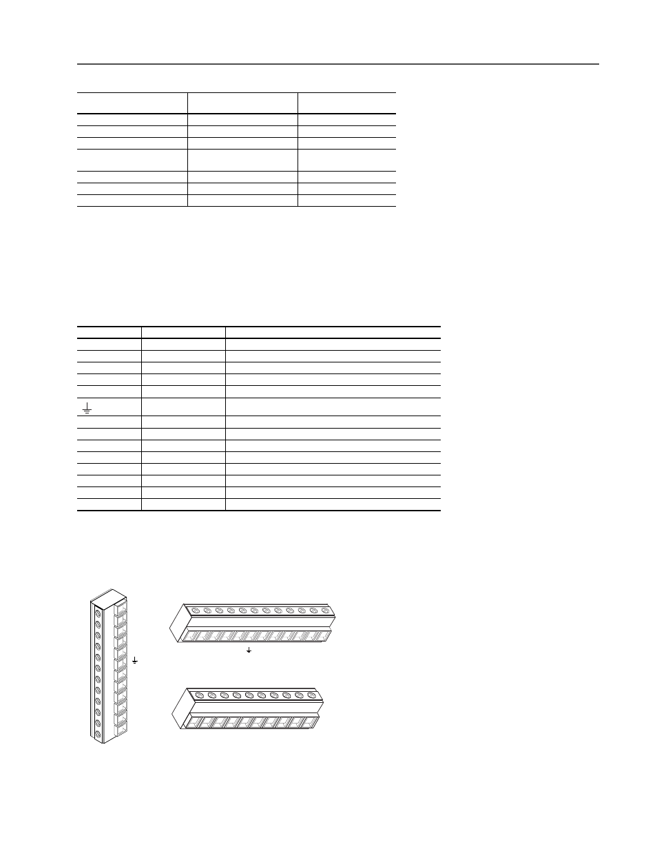
Frames 1 - 4 Power Terminal Blocks
Drive Frame
Size
Max./Min. Wire Size
(4)
mm2 (AWG)
(4)
Wire sizes given are maximum/minimum sizes that TB1 will accept - these are not recommendations.Use Copper
wire only. Wire gauge requirements and recommendations are based on 75 degree C. Do not reduce wire gauge
when using higher temperature wire.
Maximum Torque
N-m (lb.-in.)
B1
8.4/0.8 (8/18)
1.81 (16)
B2
13.3/0.5 (6/20)
1.70 (15)
C
26.7/0.8 (3/18)
5.65 (50)
D
(1), (2)
(1)
These configurations of TB1 are stud type terminations and require the use of lug type connectors to terminate field
installed conductors. Lug kits are available for use with these configurations. Wire size used is determined by
selecting the proper lug based on the drive catalog number.
(2)
One TE terminal is present – Max./Min. Wire Size is the same as other terminals.
120.0/2.1 (4/0 /14)
67.4/2.1 (00/14)
(5)
(5)
Applies to 30 kW (40 HP) 200-240V, 45 & 56 kW (60 & 75 HP) 380-480V, 56 kW (75 HP) 500-600V drives only.
6.00 (52)
6.00 (52)
E
(1), (3)
(3)
Two TE terminals are present – Max./Min. Wire Size is the same as the D Frame terminal block.
253.0/2.1 (500 MCM/14)
10.00 (87)
F
(1)
303.6/2.1 (600 MCM/14)
23.00 (200)
G
(1)
303.6/2.1 (600 MCM/14)
23.00 (200)
Terminal
Description
Notes
BR1
DC Brake (+)
Dynamic Brake Resistor Connection (+)
BR2
DC Brake (–)
Dynamic Brake Resistor Connection (–)
DC+
DC Bus (+)
DC Input Power or Dynamic Brake Chopper
DC–
DC Bus (–)
DC Input Power or Dynamic Brake Chopper
PE
PE Ground
Not present on 3 Frame drives
Motor Ground
Not present on 3 Frame drives
PS+
Aux +
(1)
(1)
External control power: UL Installation - 300V DC,
±
10%, Non UL Installation - 270-600V DC,
±
10%. Frames 1-3; 40 W, 165
mA, Frame 5; 80 W, 90 mA
PS-
Aux -
(1)
U
U (T1)
To motor
V
V (T2)
To motor
W
W (T3)
To motor
R
R (L1)
AC Line Input Power
S
S (L2)
AC Line Input Power
T
T (L3)
AC Line Input Power
BR1
BR2
DC+
DC–
PE
U (T1)
V (T2)
W (T3)
R (L1)
S (L2)
T (L3)
T
(L3)
S
(L2)
R
(L1)
W
(T3)
V
(T2)
U
(T1)
DC–
DC+
BR2
BR1
Frame 1
Frame 2
Frames 3 & 4
T
(L3)
S
(L2)
R
(L1)
W
(T3)
V
(T2)
U
(T1)
PE
DC–
DC+
BR2
BR1