L1, l2, l3 ac, Ac input, Ac input (f rom abo ve) – Rockwell Automation 23P PowerFlex DC Stand Alone Regulator and Gate Amplifier User Manual
Page 53: Gate amplif er, Pow erfle x dc stand-alone regulator
Rockwell Automation Publication 23P-UM001D-EN-P - July 2012
53
Gate Amplifier Installation and Wiring
Chapter 3
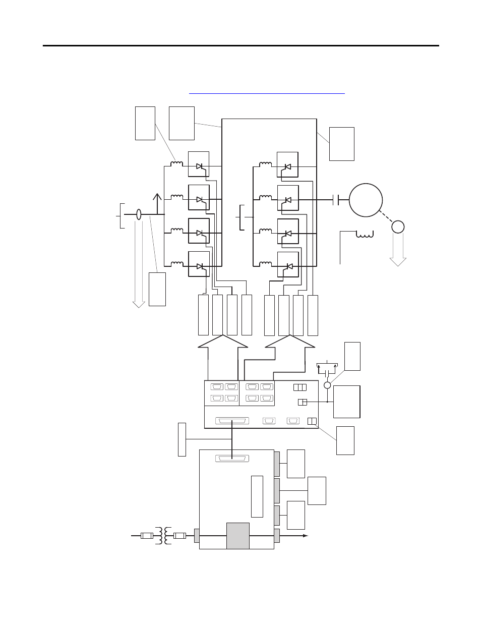
Figure 20 - Typical Gate Amplifier Interface to Multiple S6Rs
REV
GA
TES
REV
GA
TES
FWD
GA
TES
48V Ext P/S
(If Required)
To Stop
Circuitr
y
P/S
MONIT
OR
RELA
Y
GA
TE COUPLER
ASSEMBL
Y
GA
TE COUPLER
ASSEMBL
Y
GA
TE COUPLER
ASSEMBL
Y
GA
TE COUPLER
ASSEMBL
Y
GA
TE COUPLER
ASSEMBL
Y
GA
TE COUPLER
ASSEMBL
Y
GA
TE COUPLER
ASSEMBL
Y
GA
TE COUPLER
ASSEMBL
Y
L1, L2, L3
AC
CT FDBK to PFDC SAR
AC
Input
F
rom PFDC
Regulator
Motor Field
Motor
M
+DC and -DC
P
ow
er Module
Output
A
C Input (F
rom Abo
ve)
CTs on
L1 and L3
AC
T
o
Re
verse Br
idges
(Belo
w)
+DC and -DC
P
ow
er Module
Output
FWD
4
FWD
3
FWD
2
FWD
1
REV
4
REV
3
REV
2
REV
1
To Encoder or Resolv
er F
eedbac
k P
or
t
Encoder or Resolv
er F
eedbac
k
+
-
SD3K
FWD IN
SD3K
REV IN
PFDC
Gate Input
FWD
REV
RD
Y
Ext.
P/S
120V
A
C
Gate Amplif
er
Load Share
Reactors
P
ow
erFle
x DC
Stand-alone Regulator
KPT11
(15 Pin D-Shell)
Field Supply
40 A or 70 A
(2 Quad)
To Motor
Field
Gate Cab
le
Nor
mally
Open Contacts
to Stop Circuitr
y
C1 D1
D C
W
V U
1A1 A1 1A2 A2
1 2 3 4 5 6 7 8
KPT31
KA
KP
P
ow
er Module
A
C / DC
F
eedbac
k
P
ow
er Module
Ar
mature V
oltage
F
eedbac
k
P
ow
er Module
Ther
mostat and
CT F
eedbac
k
V1 U1
All T
er
minals
are
located
on the bottom of the unit.
See
Parallel Power Modules and Load Share Reactors on page 65
for more information.