Current transformer connections – Rockwell Automation 23P PowerFlex DC Stand Alone Regulator and Gate Amplifier User Manual
Page 24
24
Rockwell Automation Publication 23P-UM001D-EN-P - July 2012
Chapter 2 Stand Alone Regulator Installation, Wiring and Configuration
Power Module Thermal
Switch and Current
Transformer Wiring
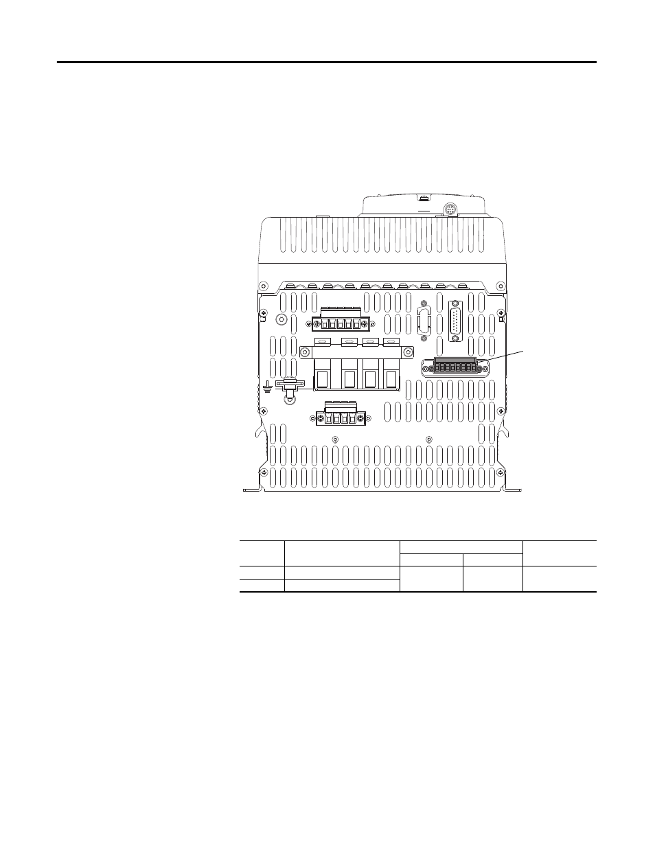
Connector KPT31 is used for power module thermal switch monitoring and
current feedback via current transformer connections. Note that the thermal
monitor circuit includes a thermal switch on the field power module within the
SAR.
Figure 8 - Power Module Thermal Switch and Current Transformer Terminal Block
(KPT31)
Table 6 - Power Module Thermal Switch and Current Transformer Terminal
Specifications
Current Transformer Connections
Current transformer 1 (CT1) monitors the U phase, with the “+” output of CT1
connected to terminal 5 of KPT31 and the “-” output of CT1 connected to
terminal 6 of KPT31.
Current transformer 2 (CT2) monitors the W phase, with the “+” output of
CT2 connected to terminal 7 of KPT31 and the “-” output of CT2 connected to
terminal 8 of KPT31.
The “-” side of the CTs are connected together internally in the SAR.
Terminal Description
Wire Size Range
Recommended
Torque
Maximum
Minimum
1, 2, 3
Thermal Switch Monitor
(1)
(1) These terminals are jumpered by default. The jumper wires must remain in place if a power module thermal
switch is NOT connected.
2.5 mm
2
(12 AWG)
0.2 mm
2
(24 AWG)
0.5…0.6 N•m
(4.4…5.3 lb•in)
5, 6, 7, 8
Current Transformer Feedback
1A1
(C)
A1 1A2
(D)
A2
V1 U1 C1 D1
D C W V U
KPT21
KPT11
KPT31
PE
1 2 3 4 5 6 7 8
Power Module
Thermal Switch and
Current Transformer
(KPT31) Terminal
Block
Bottom View of SAR