Sta nd al on e r eg ul ato r ( s ar) – Rockwell Automation 23P PowerFlex DC Stand Alone Regulator and Gate Amplifier User Manual
Page 19
Rockwell Automation Publication 23P-UM001D-EN-P - July 2012
19
Stand Alone Regulator Installation, Wiring and Configuration
Chapter 2
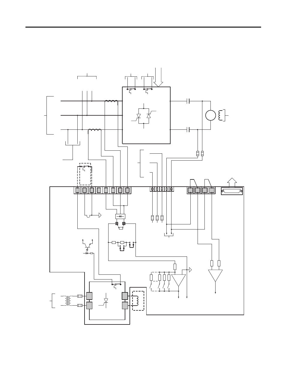
Figure 4 - Typical Stand Alone Regulator Interface to S6R Power Module
Pw
r M
od
/ Arm Fdbk
Conn
“KA
”
2
1
3
4
5
6
7
8
Pw
r M
od
T
he
rm
al
/ CT Feedback
Conn
“KPT31
”
U
(L1)
U
VW
MM
M
Int
er
nal
F
us
es
Fr
om
A
C
Li
ne
A
bov
e
To
S
AR
Co
nn
“
KP
”
Faul
t
To
S
AR
Co
nn
“
KPT31
”
W
ar
ni
ng
To
D
ig
it
al
I/O
(if available)
Fi
el
d R
egul
at
or
(2
Q
uad)
U
V
To
Fie
ld
P
ow
er
Module
Transformer
In
co
min
g A
C
L
in
e
Fr
om
I
nc
om
ing A
C
Li
ne
Tr
ans
for
m
er
(External to
S
AR)
Fi
el
d P
M
T
he
rm
OT
+15
V
IS
O
+
-
Mo
to
r F
ie
ld
Mo
to
r F
ie
ld
S
uppl
ied by
S
AR
Field Power Module
(or separately excited)
U1
V
1
C1
D1
Ex
t.
Rb
XC
T
J4
J5
Ar
m
at
ur
e
C
ur
rent
Feedback
Ga
te
I
np
ut
Ga
te
s
Ga
te
Ou
tp
ut
Conn
“KPT11
”
To
Gate Amplifier
(refer to gate wiring
diagrams)
S
ta
nd
Al
on
e
R
eg
ul
ato
r (
S
AR)
* No
te
: Armature
V
oltage
Feedback. Jumpers
must always be in place.
Fr
om
G
ate
Am
pl
if
ie
r O
utp
ut
(r
ef
er
t
o gat
e
w
ir
ing di
agr
am
s)
Ar
m
at
ur
e
V
oltage
Feedback
S
ee page 21 for
Fuse
S
izes
(External to
S
AR)
Mo
to
r A
rm F
db
k
“-
” A2
(PM Out -
“D
”) 1A2
M
ot
or
A
rm
F
dbk
“
+”
A1
(PM Out +
“C
”) 1A1
AC / DC Feedback
Conn
“KP
”
D,
“-
”
C,
“+
”
W
, AC_In
V
, AC_In
U, AC_In
CT2 -
CT2 +
CT1 -
CT1 +
(Not_Used)
Therm_Com
IS
O_Com
+V
_Therm, +15
V
0V
IS
O
#S
2
(Test
Pt.)
2.5
Ohms
2.5
Ohms
Ther
m
Fault
On Pwr Mod
V
(L2)
W
(L3)
U, (L1)
V
, (L2)
W
, (L3)
CT1
CT2
U
(L1)
V
(L2)
W
(L3)
“+
”
C
“-
”
D
5A, 700
V
5A, 700
V
*(
S
ee
Note)
*(
S
ee
Note)
To
V
oltage
Feedback
Circuits