Field power module bridge and ground wiring – Rockwell Automation 23P PowerFlex DC Stand Alone Regulator and Gate Amplifier User Manual
Page 20
20
Rockwell Automation Publication 23P-UM001D-EN-P - July 2012
Chapter 2 Stand Alone Regulator Installation, Wiring and Configuration
Field Power Module Bridge
and Ground Wiring
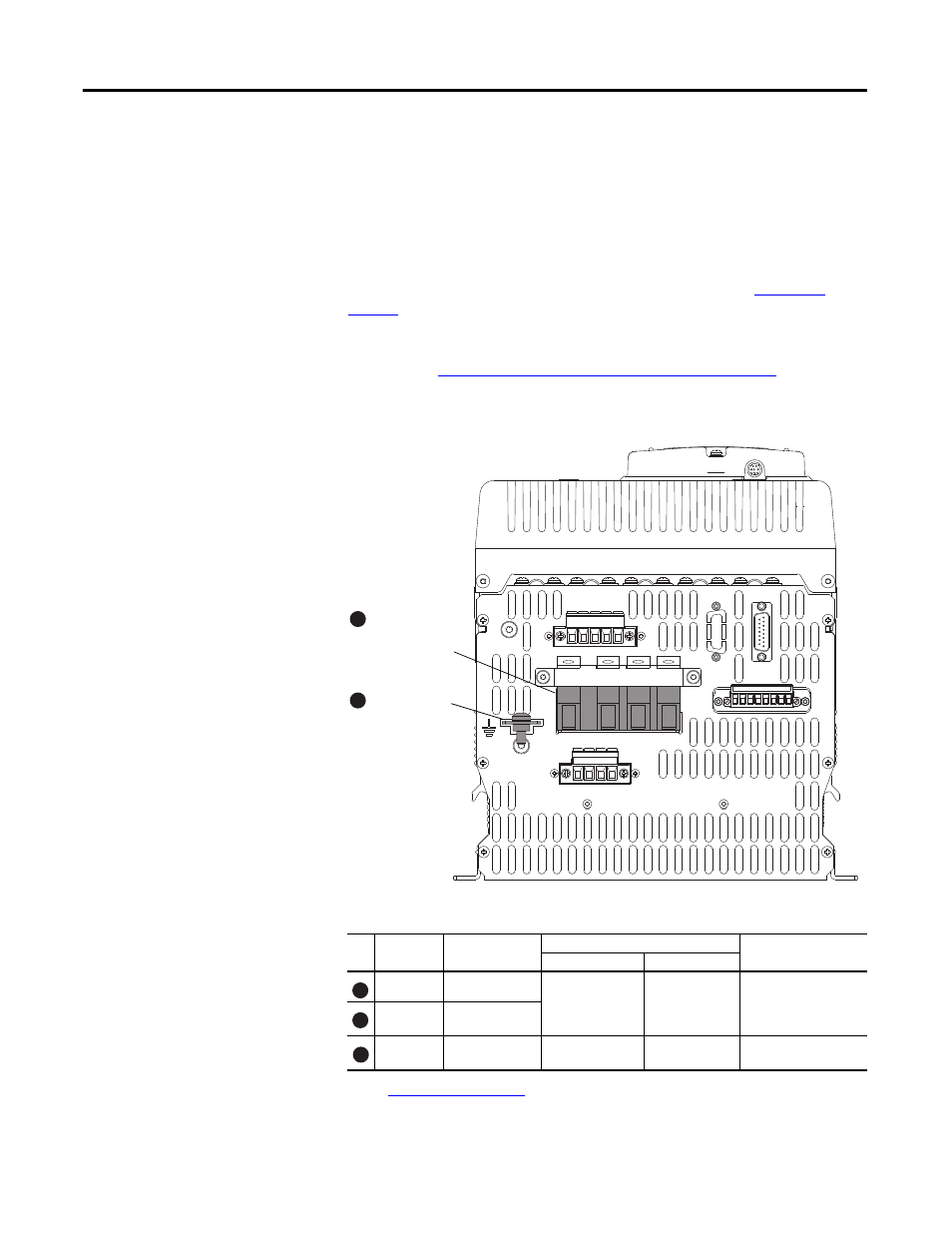
The SAR contains a two quadrant field power module bridge. The field bridge
input circuit is rated for 100VAC…460VAC, ±10%, 50/60 Hz. The input and
output connections to/from the field bridge are on the bottom of the SAR as
shown.
An external transformer with appropriate primary fusing is required to supply the
field. External fusing is also required at the input terminals V1 and U1 to protect
the field bridge. The recommended fuse types are shown in the
.
The SAR motor field current must configured with a hardware DIP switch and in
firmware. See
SAR Motor Field Current Configuration on page 26
for more
information.
Figure 5 - Field Power Module Bridge Terminal Block and Ground Connection
Table 3 - Field Power Module Bridge and Ground Terminal Specifications
No. Terminal
Description
Wire Size Range
Recommended
Torque
Maximum
Minimum
V1, U1
AC Input Power
25.0 mm
2
(2 AWG)
10.0 mm
2
(10 AWG)
4.0…4.5 N•m
(35.4…39.8 lb•in)
C1, D1
DC Output Power
to Motor Field
PE
Safety Ground
(1)
(1) See
16.0 mm
2
(6 AWG)
10.0 mm
2
(8 AWG)
6.0…8.0 N•m
(53.1…70.8 lb•in)
1A1
(C)
A1 1A2
(D)
A2
1 2 3 4 5 6 7 8
V1 U1 C1 D1
D C W V U
KPT21
KPT11
KPT31
PE
Field Power
Module Bridge
Terminal Block
PE Terminal
Bottom View of SAR
1
2
1
1
2