Converterpac functional description – Vicor Westcor PFC MegaPAC Power Factor Corrected AC-DC Switchers User Manual
Page 6
UG:105
vicorpower.com
Applications Engineering: 800 927.9474
Page 6
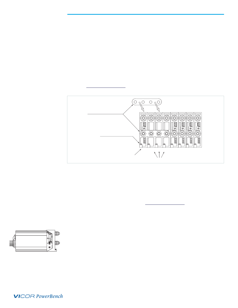
Installing Booster ConverterPACs to Increase Output Power
ConverterPACs can be paralleled for more power. Additional power to an output is
obtained by connecting one or more boosters in parallel with a single driver. The
driver can be placed in any open slot. All boosters should be inserted in the slots to
the immediate right of the driver as viewed from the output end of the MegaPAC.
Figure 2 shows a driver placed in slots #1 and 3 boosters placed in slots # 2 to 4. After
inserting the driver and boosters, they are paralleled using bus bars across the positive
and negative output studs. Drivers should not be paralleled with each other. Bus bars
between a driver and booster (s) should never be disconnected. For help in identifying
boosters and drivers, refer to the Part Numbering section on page 8. Please note that
total output voltage should not exceed the converter baseplate-output isolation rating of
400 V. For detailed guideline on how outputs should be placed in series, please refer to
the Applications note (Creating high voltage outputs) available on the
website at
ConverterPAC Functional Description
ConverterPACs are the family of slide-in output assemblies used in MegaPAC power
supplies. Most ConverterPACs of the same length are interchangeable within a
MegaPAC and between different AC input MegaPAC chassis (Exceptions are the FinPAC
and UniPAC). They can be added, moved, or changed as necessary. The following
ConverterPACs can be used in the PFC MegaPAC and/or PFC MegaPAC-High Power.
Spec sheets for ConverterPACs are available at
ModuPAC
The ModuPAC output assembly consists of a VI-200 DC to DC converter that converts
the high voltage bus to the desired regulated output voltage. Each ModuPAC can provide
up to 200 Watts of power. Multiple ModuPACs can be paralleled in a driver-booster
configuration to provide more power. ModuPACs are fused with a PC-Tron, DC-rated,
fast-acting fuse. A passive LC filter is used to reduce output ripple/noise down to 1%
typical, and 2% maximum peak-to-peak from 10% to 100% of rated load. An optional
DC Power Good signal, or output voltage Trim potentiometer can be specified. The
ModuPAC contains overvoltage protection (OVP), overcurrent protection (OCP), and
overtemperature limiting (OTL). The OCP has automatic recovery when the overcurrent
condition is removed. The OVP and OTL are latching functions and require recycling of
the AC input power to restart.
Figure 2.
Paralleling ConverterPACs
Driver
Bus Bars for Paralleling
Loosen screw to
remove ConverterPAC
Boosters
1
2
3
4
5
6
7
8
+
_
Remote Sense
VI-200
Output Adjust
- Vout
+ Vout
DC OK (Power Good)
ModuPAC