Vicor Westcor PFC MegaPAC Power Factor Corrected AC-DC Switchers User Manual
Page 19
UG:105
vicorpower.com
Applications Engineering: 800 927.9474
Page 19
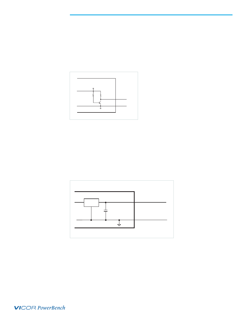
Figure 7.
AC OK Power Fail
AC OK / Power Fail (J10-11)
This is an active high TTL compatible signal and provides a status indication of the AC
input power (see Figure 7 and Connector Pin Identification on page 14). It is capable
of sourcing 0.5 mA at >3.2 V and sink 16mA at < 0.5 V. This signal switches to a TTL “1”
when the high voltage bus exceeds low-line condition during turn-on, and switches
to a TTL “0” 3 ms (minimum) before loss of output regulation due to the loss of input
AC power. This signal can be used to warn external control circuits of an
impending loss of power.
Auxiliary Vcc +5V/0.3A (J10-9)
The Vcc on J10-9 is an auxiliary 5 V regulated power source (see Figure 8 and Connector
Pin Identification on page 14). It is +5 Vdc +/–5% with respect to Signal Ground and can
supply 300 mA maximum. It is short-circuit-proof, but if shorted all outputs will shut
down through the Enable/Disable circuitry. The Auxiliary Vcc typically powers user
circuitry or is used with the Power Good circuitry to provide a pull-up reference for the
outputs of the DC Power Good circuit on a ConverterPAC. If used for this purpose, the
Signal Ground on J10-10 must also be connected to the J3-1 Signal Ground pin
of the ConverterPAC.
10K
Signal Ground
AC Power OK
11
+5V
10
J10
2.49K
PN2222
Figure 8.
Auxiliary Vcc
78M05
Auxiliary Vcc
9
0.1 µF
Signal Ground
J10
10
+5V/300 mA