Vicor Westcor PFC MegaPAC Power Factor Corrected AC-DC Switchers User Manual
Page 17
UG:105
vicorpower.com
Applications Engineering: 800 927.9474
Page 17
Signal Ground (J10-10)
Signal Ground (see Figure 4 and Connector Pin Identification on page 14) is an isolated
ground reference for all J10 interfacing signals, and can be used for ConverterPAC
output status signals such as Power Good. This is not the same as Earth Ground on input
power connector J9.
Enable/Disable (J10-1 to J10-8)
The Enable/Disable control pins allow ConverterPAC outputs to be sequenced either
on or off. J10-1 through J10-8 are the control pins for output positions 1 through 8,
respectively (see Figure 5 and Connector Pin Identification on page 14). For DualPACs
and FlexPACs, all outputs are sequenced. In parallel array using VI/VE modules only
the driver ConverterPAC need be controlled. The Enable/Disable pins should be pulled
low to less than 0.7 V with respect to Signal Ground to disable the outputs. They will
sink 10 mA maximum. These pins should be open circuited or allowed to exceed 4.5 V
when enabled. Do not apply more than 6 V to these inputs at any time. If driven from
an electromechanical switch or relay, a capacitor should be connected to eliminate the
effects of switch bounce.
Figure 4.
Interface Connector
12
11
10
9
8
7
6
5
4
3
2
1
J10
J10-9
J10-10
J10-11
J10-12
Vcc +5V, 0.3A
SIGNAL GROUND
AC POWER OK
GEN SHUTDOWN
J10-1
J10-2
J10-3
J10-4
J10-5
J10-6
J10-7
J10-8
E/D-1
E/D-2
E/D-3
E/D-4
E/D-5
E/D-6
E/D-7
E/D-8
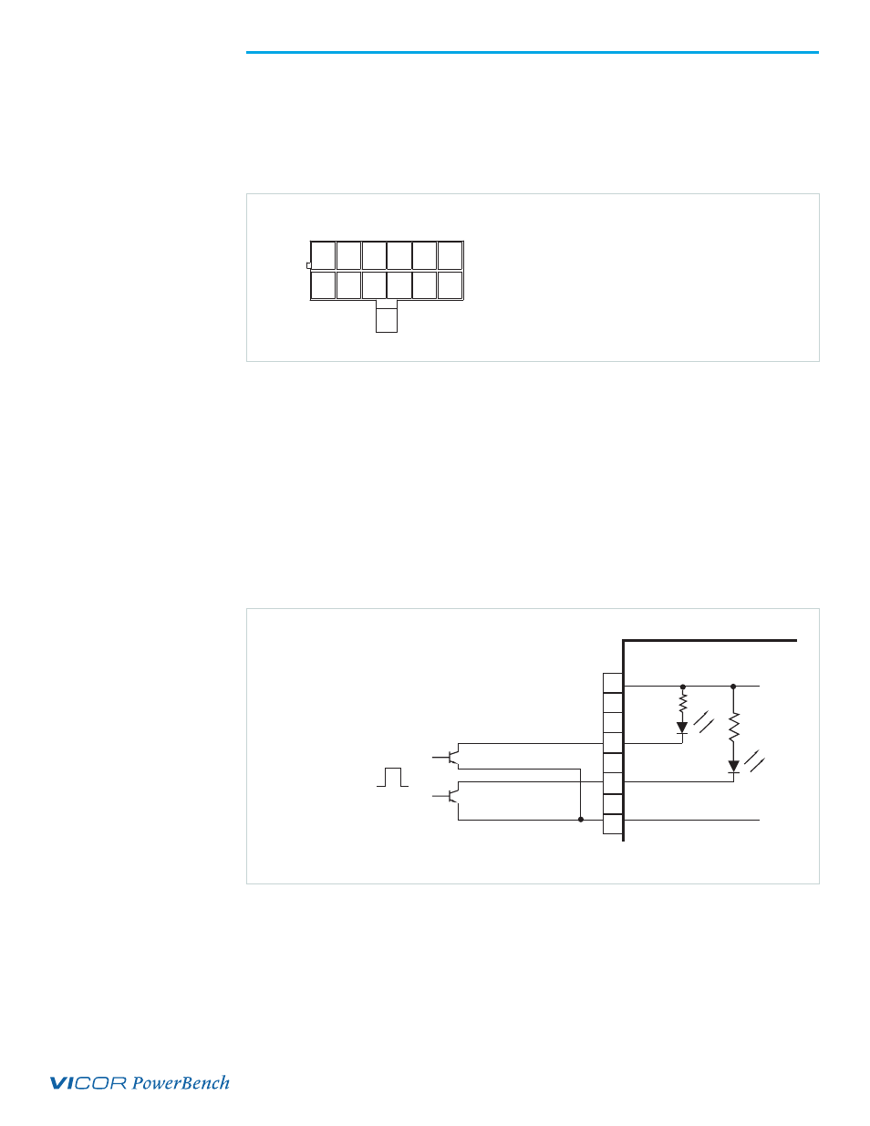
Figure 5.
Enable/Disable and
General Shutdown
PFC MegaPAC
1
10
12
Signal Ground
General Shutdown
Enable/Disable Output 1
J10
1
0
TTL "1" (OFF)
TTL "0" (ON)
A TTL "1" applied to the base of the transistor turns
output OFF. Pin 1 (or Pin 12 for GSD) is pulled Low
with respect to Signal Ground.
9
Vcc