Configuring and reconfiguring megapacs – Vicor Westcor PFC MegaPAC Power Factor Corrected AC-DC Switchers User Manual
Page 5
UG:105
vicorpower.com
Applications Engineering: 800 927.9474
Page 5
The ride-through (holdup) time is the amount of time the load can be supported before
loss of output regulation after the loss of input power. Detecting the loss of input power
takes a finite time period after which the AC Power OK signal goes from a TTL “1” to “0."
This signal is available for use within 1.2 seconds after initial power-up and can be used
to indicate an impending loss of power. At least 3 ms of warning time is given. Following
the loss of input power, the outputs are disabled when the bus voltage drops below its
operating threshold.
Configuring and Reconfiguring MegaPACs
Most ConverterPACs of the same length can be inserted into any available slot of a
MegaPAC chassis. They can also be easily added, replaced, or moved by sliding the
assemblies in or out of a MegaPAC chassis. (Currently, two exceptions are the FinPACs
which can only be used in the high power chassis and the UniPACs which can only be
used in the 4 kW MegaPAC.) For outputs greater than 200 Watts, a driver ModuPAC
and one or more booster ConverterPACs will be used. For outputs greater than
600 Watts, a driver FinPAC and one or more booster ConverterPACs will be used.
Arrays of drivers and boosters should be configured so all boosters are placed in the slots
to the immediate right of the driver when looking at the output end of the MegaPAC.
Prior to removing or installing ConverterPACs, you must remove power from the
MegaPAC and wait 5 minutes. Failure to do so can result in personal injury or
damage to the supply.
Take standard ESD precautions when handling ConverterPACs.
Removing ConverterPACs
ConverterPACs can be removed by loosening the captive screw at the base. Once
this screw has been loosened, the ConverterPAC will slide out of the chassis. Once a
ConverterPAC has been removed, the empty slot MUST be filled with either another
ConverterPAC or an airblock. If the slot is left empty, it will provide an airflow escape
and cause failure to the power supply.
Installing ConverterPACs as Drivers
ConverterPACs can be installed in empty slots by simply sliding in the new
ConverterPAC and securing the screw at the base. Power and interface connections can
be made after the ConverterPAC has been installed.
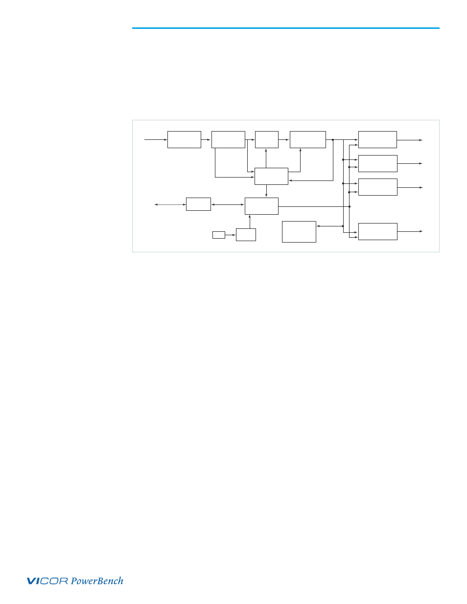
Line Filter
Rectifier
Soft Start
Circuit
Boost Converter
PFC Control
E/D Control
ConverterPAC #1
ConverterPAC #2
ConverterPAC #3
ConverterPAC #8
Fan
Housekeeping
Power
Current
Monitor
Customer
Interface
Power
Output
Power
Output
Power
Output
Power
Output
Input
High Voltage
DC Bus
Enable/Disable Control
Current
Sample
Waveform
Sample
Figure 1.
PFC MegaPAC and PFC
MegaPAC-High Power
Architecture