Interface connections, Figure 3. input panel connectors – Vicor Westcor PFC MegaPAC Power Factor Corrected AC-DC Switchers User Manual
Page 16
UG:105
vicorpower.com
Applications Engineering: 800 927.9474
Page 16
Interface Connections
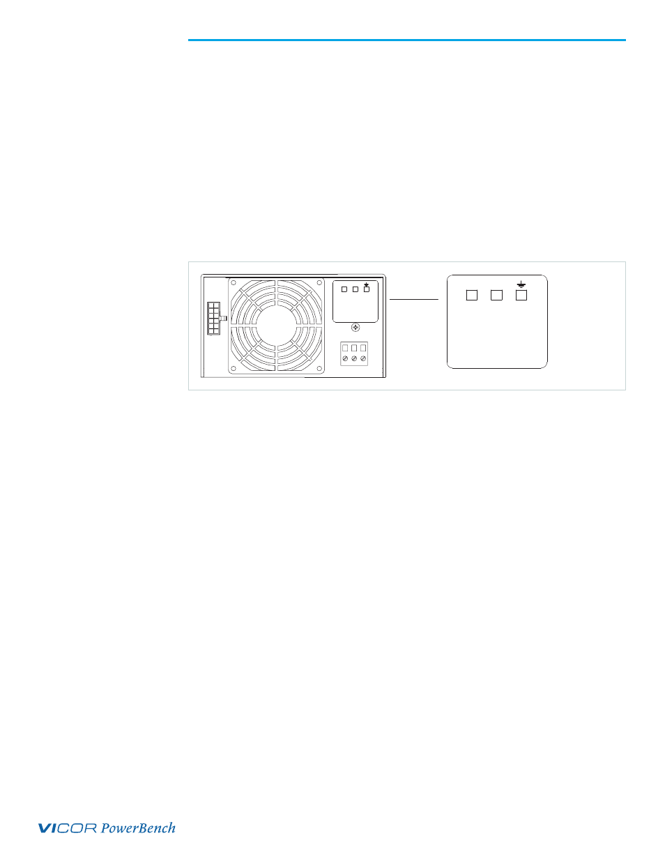
Chassis Input Power Terminals (J9)
Input AC power is applied to terminal block J9 using a pressure screw terminal that
accepts a maximum wire size of 14 AWG. The insulation should be stripped .35 inches
and the maximum torque applied to the screws should not exceed 4.4 lb-in. The
connector manufacturer recommends the wires not be tinned. A ferrule (Phoenix P/N
32-00-58-0, purchased from other sources) can be used to prevent fraying. J9-1 (GND) is
Earth Ground for safety; J9-2 (L2) and J9-3 (L1) are the other Hot connections. For Input
DC power, L2 is (+) and L1 is (-).
A fault clearing device, such as a fuse or circuit breaker with a maximum 15A rating at
the power supply input is required for safety agency compliance. It should be sized to
handle the start-up inrush current of 25A pk at 115 Vrms and 230 Vrms.
Output Power Connections (+P, -P for Single Output, or J1A/J1B for Dual Outputs)
For single output ConverterPACs, these terminals are two 1/4-20 plated steel studs. The
upper stud is positive with respect to the lower stud. For dual output ConverterPACs,
there is a 6-pin Molex connector for each output. J1A pins 1 and 4 are the +Output,
and J1A pins 2 and 5 are the -Output. Pins 3 and 6 are duplicates of the Remote Sense
terminals present on J2A and J2B. Use appropriate wire size rated to handle the full
output current, including short circuit levels. Avoid large current loops in output cables;
run power and return cables next to one another to minimize inductive effects. All
outputs are isolated and can provide positive or negative outputs.
Output +/-Sense Connections -J2 for Single Output, or J1A/J1B for Dual Outputs
Newer power supplies may have some outputs configured with the Autosense feature
that automatically locally senses the output if remote sense is not used. To check if an
output has the Autosense feature, measure the impedance from the + Out to + Sense and
- Out to - Sense pins. If the impedance is 5 ohms, then the output has Autosense and
does not require local sense jumpers. FlexPAC is local sense only.
If units do not have Autosense, sense connections must be made. When making
sense connections, keep in mind that although all outputs are open-Sense protected,
the +/-Sense terminals must be connected to their respective outputs before the PFC
MegaPAC and PFC MegaPAC-High Power are powered up. Regardless of the output
polarity configured, the +Sense should always connect to the +Power output. The
-Sense connects to the -Power output. Sense connections are not required on booster
ConverterPACs, BatPACs, or if the Local Sense option is specified. Local Sense mode
means that the Remote Sense lines are not connected. Sense pins can be accessed on
J1A/J1B or J2A/J2B on dual output units.
INPUT CONNECTIONS
J9-1 EARTH GROUND
J9-2 L2-NEUTRAL
J9-3 L1
INPUTS
DO NOT
WITHOUT
EARTH
GROUND
L2
115/230 VAC
300VDC
47 TO 500 Hz
OPERATE
NOTE: SET SCREW MAXIMUM
TORQUE = 4.4 INCH POUNDS
LABEL NO: 94-00046 REV B
L1
u
INPUTS
DO NOT
WITHOUT
EARTH
GROUND
L2
115/230 VAC
300VDC
47 TO 500 Hz
OPERATE
NOTE: SET SCREW MAXIMUM
TORQUE = 4.4 INCH POUNDS
LABEL NO: 94-00046 REV B
L1
Figure 3.
Input Panel Connectors